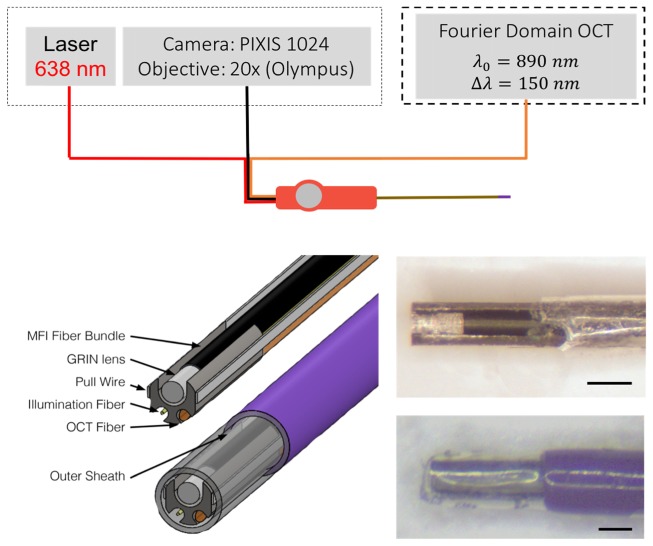
Fig. 1.
System overview (top) and distal tip overview (bottom left) showing detailed inner components and the orientation in the sheath. The illumination fiber is shown in red (top) and in gold (bottom left), the OCT fiber in orange, and the fiber bundle in black. In this iteration, we use a single 638nm fiber coupled laser for illumination and image the proximal fiber bundle face onto a PIXIS camera. The OCT probe is incorporated as the sample arm into an existing tabletop OCT system. The distal tip uses a ferrule (grey) to hold the components (fiber bundle, GRIN lens, two pull wires, illumination fiber and OCT fiber). These inner components are within the outer sheath of heat shrink (clear tip) and polymer (purple). Photos of the probe are shown (bottom right) with the heat shrink peeled back (top) to reveal the optics and with the heath shrink and outer sheath in place (bottom). Scale bas are 0.5 mm.

