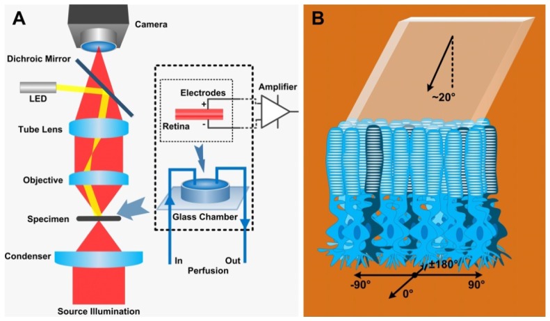
Fig. 1.
(A) Schematic diagram of the experiment setup. Left: A custom modified microscope with a 40X water immersion microscope and a CCD (100 fps) or a CMOS (500 fps) camera was employed for imaging. Right: The ERG recoding was achieved by placing electrodes on the retina in a glass chamber (dashed square). The isolated retina was continuously superfused with physiological medium during the experiment. (B) The retina was placed with photoreceptor layer on the top and was obliquely (~20°) stimulated by visible light from the top [2]. The coordinate axes shown at the bottom were used to define the direction of ROS movement. The 90° direction represents ROS movement toward the incident stimulation.

