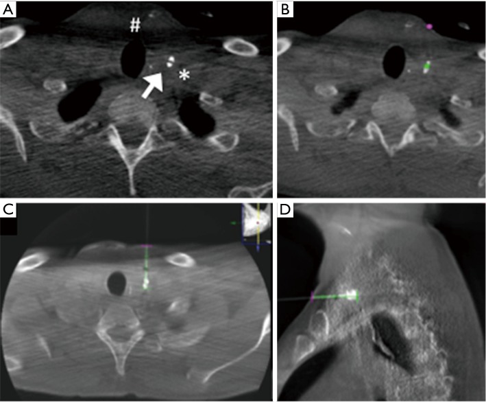
Figure 3.
(A) CBCT acquisition show contrast leak (white arrow), the surgical drainage (#) and the vascular structures (*); (B) on CBCT acquisition, operator stabilized the entry point (violet point) and the target point (green point); axial and sagittal views (C,D) of the CBCT acquisition performed after the insertion of the needle on the basis of the path (green line) calculated by the system on the basis of the entry point and target point indicated by the operator.

