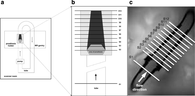
Fig. 1.

Setting of the MR flow phantom for in-vitro assessment of heart valve prostheses. a. Scheme of the experimental setting showing the closed circuit flow phantom as placed in the scanner. b. Scheme of the acrylic pipe and positioning of the measurement slices (S1-S12). c. Coronal magnitude image of the acrylic pipe, proximal and distal parts of the tube system and positioning of the measurement slices. The arrow demonstrates the direction of flow
