Abstract
Robotic systems have slowly entered the realm of modern medicine; however, outside the operating room, medical robotics has yet to be translated to more routine interventions such as blood sampling or intravenous fluid delivery. In this paper, we present a medical robot that safely and rapidly cannulates peripheral blood vessels—a procedure commonly known as venipuncture. The device uses near-infrared and ultrasound imaging to scan and select suitable injection sites, and a 9-DOF robot to insert the needle into the center of the vessel based on image and force guidance. We first present the system design and visual servoing scheme of the latest generation robot, and then evaluate the performance of the device through workspace simulations and free-space positioning tests. Finally, we perform a series of motion tracking experiments using stereo vision, ultrasound, and force sensing to guide the position and orientation of the needle tip. Positioning experiments indicate sub-millimeter accuracy and repeatability over the operating workspace of the system, while tracking studies demonstrate real-time needle servoing in response to moving targets. Lastly, robotic phantom cannulations demonstrate the use of multiple system states to confirm that the needle has reached the center of the vessel.
Index Terms: Medical robots, Motion control, Robot vision systems
I. Introduction
Medical robots have played a key role over the past decade in assisting health care practitioners to perform a wide range of clinical interventions [1], [2]. These robots are primarily used to manipulate medical instruments within the operating workspace of the procedure. In many cases, the robot’s performance depends heavily on its ability to obtain accurate information about the spatial positioning of the tools and the target. This positioning information may then be used as feedback in the robot’s motion control scheme [3], [4].
One clinical application in which positioning feedback is especially important is percutaneous needle insertion [5]. Manually introducing a needle blind through soft tissue can be challenging when solely relying on anatomical landmarks or haptic cues. Success rates often depend on the experience of the practitioner and the physiology of the patient, and poorly introduced needles can result in damage to the surrounding tissue that may lead to a wide range of complications [6]. To augment the needle insertion process, various imaging modalities may be utilized before the procedure to plan the path of the needle, or during the procedure to servo the needle in real-time. To date, the majority of research in needle insertion robotics has focused on complex surgical procedures.
For example, Kobayashi et al. described a needle insertion surgical robot, combining force sensing and US imaging for central venous catheterization [7], [8]. Tanaka et al. combined vision-based position and force information in a bilateral control system to achieve haptic feedback in an endoscopic surgical robot [9]. Numerous research groups have also studied needle–tissue interactions during percutaneous surgical interventions with the use of robotic systems [10]–[14].
Outside the operating room, the most commonly performed percutaneous needle insertion procedure is peripheral vessel cannulation, or venipuncture. Over 2.7 million venipuncture procedures are carried out each day in the United States, for the purpose of collecting blood samples or delivering vital fluids to the peripheral circulation [15], [16]. Near-infrared (NIR) and US-based imaging systems may be used to help practitioners identify suitable vessel targets. However, because these devices still rely on the clinician to insert the needle, the accuracy rate of the actual needle placement is not significantly increased compared to manual techniques [17]–[19]. One group has described adapting an industrial-sized, commercial robotic arm to perform venipuncture. The system incorporates the imaging (mono-camera and US) and needle insertion mechanism on the end-effector of the industrial arm. Reports have indicated that the device can locate a suitable vein about 83% of the time [20]; however, this data excludes success rates for the robotic needle insertion. Moreover, the size and weight of the robotic arm may greatly inhibit clinical usability of the system.
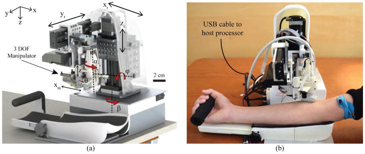
Meanwhile, our group has described a compact (<10 cubic in.) and lightweight (<5 kg) robotic device, the VenousPro (Fig. 1), that is designed to perform venipuncture procedures in a wide range of clinical settings in an automated fashion [21]–[23]. The device uses a combination of 3-D NIR and US imaging to localize blood vessels under the skin, and a portable robot that orients and inserts the needle based on position information provided by the imaging systems.
Fig. 1.
(a) Conceptual design (CAD render) of the robotic system; and (b) implementation of the device during a simulated human venipuncture. Longitudinal orientation of the US transducer shown here as an alternative to the transverse orientation in (a).
Two early prototypes of the VenousPro have been previously described. The most recent consisted of 7-DOF [22]. A 3-DOF Cartesian gantry positioned the imaging components, and a 4-DOF serial arm guided the needle into the vein. The previous systems have been evaluated in human imaging trials and in vitro phantom studies, and have shown significantly improved vessel visualization and cannulation success rates compared to manual control experiments. The prototypes have also demonstrated sub-millimeter accuracy in free-space positioning experiments. However, despite these promising results, several limitations in the robotic design were observed. First, the previous systems lacked the ability to align both the needle insertion and imaging subsystems with the vessel since the imaging components were positioned by a gantry system. Thus, while the device could be tested on phantom models with parallel, unidirectional vessels, human cannulations would have been difficult due to the wide range of vessel orientations in people. Second, the previous devices lacked a radial degree of rotation allowing the robot to reach lateral vessels on the sides of the forearm. As a result of the missing degrees of motion, the previous prototypes were unable to fully utilize the combined NIR and US image information to adjust the position and orientation of the needle in 3-D space. This kinematic control is critical in allowing the system to adapt to gross arm motions and subtle vessel movements during the insertion.
Here we describe the development of a third generation (third-gen) automated venipuncture device, which provides significant advancements over previous prototypes that are critical for eventual clinical translation. The device combines 3-D NIR and US imaging, computer vision and image analysis software, and a 9-DOF needle manipulator within a portable shell. The device operates by mapping the 3-D position of a selected vessel and introducing the needle into the center of the vein based on real-time image and force guidance.
The advancements introduced in this paper include the following. First, the mechanical configuration of the third-gen system is completely redesigned to incorporate the added DOF without compromising portability. Second, the NIR, US, and needle insertion subsystems are integrated into a compact end-effector unit that allows each subsystem to remain aligned regardless of the end-effector orientation. Third, a force sensor is coupled to the motorized needle insertion mechanism as an added method of feedback during the venipuncture. Fourth, a new kinematic model is introduced to reflect the eye-in-hand configuration of the camera system, and separate motion control schemes are implemented that utilize the stereo vision, US, and force measurements to adjust the needle orientation in real-time. Finally, experimental results are provided that measure the positioning accuracy and speed of the robot under each mode of guidance.
The paper is organized as follows. Section II describes the system architecture, robotic design, and kinematic controls of the third-gen device. In Section III, we present experimental results from needle positioning studies and motion tracking under each mode of feedback, and lastly, Section IV discusses conclusions and future work.
II. System Design
The protocol to perform a venipuncture using the device begins with disinfecting the forearm and applying a tourniquet. The device then scans the patient’s forearm, using the NIR system to create a 3-D map of the vessels and estimate their depth below the skin. Once a cannulation site is selected by the clinician via the graphical user interface (GUI), the US probe is positioned over the site to provide a magnified cross-sectional view of the vessel and confirm blood flow. The coordinates of the cannulation site are directed to the robot, which then orients and inserts the needle. The device is comprised of three main subsystems: the host processor, base positioning system, and compact manipulator unit (which contains the imaging and needle insertion components) as described below.
A. Host Processor
The device runs off a laptop computer (i7-4710HQ 2.5 GHz CPU) serving as the host processor, communicating with the actuators and sensors via a USB bus. The image processing steps are accelerated on a embedded GPU (Nvidia Quadro K2200M), whereas all other tasks (e.g. path planning, motor and electronics control, and GUI functions) are executed on the CPU. With this architecture, the computer can perform the imaging and robotics computations at real-time frame rates using 800 MB and 500 MB of CPU and GPU memory respectively. 100 MB/s of data is communicated between the laptop and the robot via a single USB3 cable. Inside the robot, a receiver hub splits the input into 4 independent outputs that connect to the cameras, US system, base positioning system, and manipulator unit.
B. Base Positioning System
The base positioning system serves to orient the imaging and needle insertion end-effector unit over the target vessel. As illustrated in Fig. 1, the gantry includes 6-DOF—three prismatic joints and three revolute joints. The prismatic joints form a Cartesian positioner (xr, yr, and zr), whereas revolute joints α and ϕ allow the robot to align with the vein. β allows the entire robot to rotate before and after the procedure, but is not part of the kinematic geometry during the needle insertion. The α rotation is actuated by a miniature rotary stage (3M-R, NAI) positioned directly above the US probe, while the ϕ rotation is controlled by a goniometer cradle (BGS50, Newport). The use of a goniometer allows the axis of rotation to be offset from the stage and aligned with the axis of the forearm. This design is key to providing circumferential motion around the forearm to reach vessels at either side, without increasing the size of the device.
C. Compact Manipulator Unit
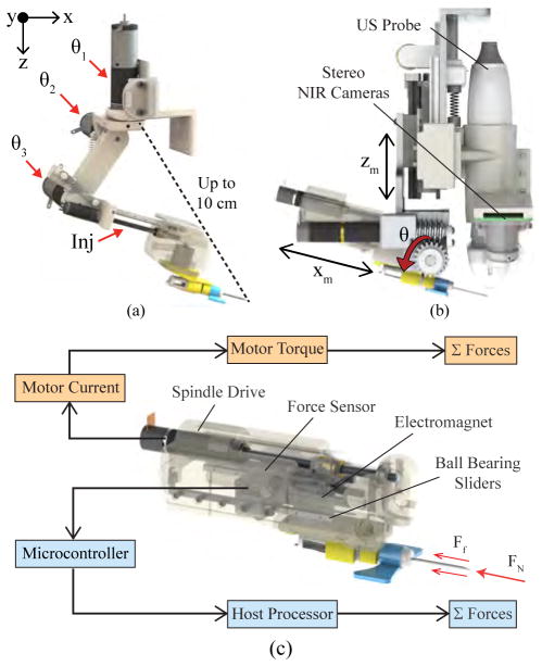
In previous designs, the base rotational joint of the serial arm manipulator (Fig. 2a), was positioned a large distance from the needle tip. Though extending the operating workspace of the manipulator, the articulated arm compromised joint stability, as minute rotational errors at the joints could lead to large positioning errors at the needle tip. While our previous studies showed that these errors could be minimized after calibrating the robot [22], relying on calibration before each use may be impractical. Furthermore, because the manipulator was not kinematically coupled with the imaging system, lateral rotations by the manipulator to align with the vessel would bring the needle out of the US image plane during the cannulation.
Fig. 2.
Needle manipulator unit. (a) 4-DOF serial arm implemented in previous designs, shown decoupled from the imaging system. Distance between the base joint and needle tip (dotted line) reached up to 10 cm at full extension, compromising joint stability. (b) The new compact manipulator coupling the redesigned needle insertion mechanism with the NIR-US imaging unit. (c) Bimodal force sensing implemented in the insertion system using a 5 N load cell (light blue), and computing force from the motor current (orange).
The design changes for the manipulator in the third-gen device are as follows. First, the new kinematic geometry allows the insertion angle (θ in Fig. 2b) to be controlled independently of the other degrees of motion. This is made possible by a linear stage that adjusts the height of the needle (zm) without affecting the height of the US probe. Combined with a servo that sets the insertion angle and a spindle drive that translates the needle (xm), the manipulator can target vessels at depths ranging from 1–10 mm below the skin surface, at insertion angles of 0–30°. Second, the distance between the needle tip and the needle’s center of rotation (curved red arrow in Fig. 1a is minimized to increase joint stability. Lastly, the lateral rotation (θ1 in the previous manipulator as shown in Fig. 2a) has been incorporated into the base positioning system (α in Fig. 1a), allowing the US probe and needle to rotate together and thereby remain in alignment at all times.
1) NIR Imaging
Two arrays of 940 nm light-emitting diodes provide NIR illumination, which allows blood vessels up to 4 mm in depth to be visualized by the cameras due to the reduced scatter of light in the NIR range. A detailed description of the NIR imaging system and computer vision software is provided in [21]. Briefly, stereo cameras mounted in an eye-in-hand configuration on the manipulator, are used to provide a 3-D map of the vasculature. Blood vessels are then segmented, and cannulation sites are ranked based on vessel geometry. Once the clinician selects the cannulation target via the GUI, the 3-D coordinates of the vessel are directed to the robot. During the cannulation, the vessel target and surrounding feature points are tracked from frame-to-frame in real-time. The feature points are selected via the SIFT algorithm [24], and only features appearing along epipolar lines in both cameras are used for tracking. The tracking approach is based on sparse optical flow [25].
To further reduce the size of the manipulator in the third-gen device, miniaturized (ø0.9 cm) NIR-sensitive cameras (VRmMS-12, VRmagic) were used. The data update rate is 40 fps for image capture, 20 fps for image processing, and 10 fps for stereo correspondence. The stereo imaging system is calibrated using a fixed planar grid with circular control points [26]. Rather than needing a separate motorized stage to adjust the height of the grid, the cameras are moved vertically via the existing zr stage, allowing the intrinsic and extrinsic camera parameters to be computed within the workspace of the robot.
2) US Imaging
The US imaging system (SmartUS, 18 MHz transducer, Telemed) provides a magnified view of the vessel and also has Doppler capabilities for blood flow detection. The US imaging is further used to visualize the needle during the insertion. The initial coordinate of the needle tip in the US image is localized automatically based on the robot kinematics, whereas the vessel center is localized initially by manual user selection. After the initial frame, both the needle tip and vessel center are tracked in subsequent frames using optical flow. The maximum B-mode image acquisition rate is 60 fps, while the image processing rate is 20 fps.
The transducer has also been reoriented on the device to provide transverse, cross-sectional imaging. In the previous prototype, the image plane of the US probe was oriented longitudinally (i.e. in the x-direction in Fig. 2). However, vessels tend to roll in the axial y-direction during the needle insertion. In these cases, the vessel would roll out of the US image plane, making it impossible for the robot to track. In contrast, the transverse orientation of the US probe allows the target vessel to be tracked over a larger cross-sectional range.
3) Force Sensing
In addition to visualizing the needle in the US image, we also implemented a force sensor in the manipulator to detect when the needle punctures the skin and vessel wall. Axial forces along the needle vary throughout the insertion due to the natural inhomogeneity of human skin tissue [27]. The sensor measures these forces, relaying information to the robotics to help compute the position of the needle tip. Especially in cases where the US image is noisy, the transducer may be unable to receive the acoustic signals from the needle. Instead, by observing the peaks in the force profile during the cannulation, we can determine the following puncture events: (1) Tissue deformation, which begins when the needle contacts the tissue and continues until the insertion force reaches a local maximum; (2) puncture, which occurs when a crack propagates through the tissue following the force peak; and (3) removal of the needle from the tissue.
The force-sensitive insertion mechanism consists of a linear stage actuated by a lead screw spindle drive (RE 8, Maxon Motors) and supported by ball bearing sliders. As the spindle translates to advance the cannula, normal and friction forces acting on the needle cause it to push against a force sensor (FSG-5N, Honeywell) embedded in the manipulator. This generates an analog signal which is then digitized by a 12-bit A/D converter. The computer simultaneously monitors the forces applied against the sensor and the electrical current running through the windings of the DC-brushed spindle drive to determine puncture events.
D. Robot Kinematics
Kinematic equations were derived using a series of matrix transforms, linking the Cartesian (xr, yr, and zr) and rotational joints (α and ϕ) of the gantry with the manipulator joint frames (zm, θ, and xm). Table I outlines the kinematic joint space of the robotic system. As mentioned earlier, the β revolute joint is independent of the needle insertion kinematics—it functions to rotate the device away from the patient, providing space for the clinician to disinfect the forearm and apply a tourniquet before the procedure and clean the device afterward.
TABLE I.
Kinematic joint space of the robotic system. Joints 1–6 comprise the gantry; 7–9 the manipulator.
| Joint | Motion | Travel Range |
|---|---|---|
|
| ||
| 1 – β | Base rotation | 0–90° |
|
| ||
| 2 – xr | Scan along arm length | 0–100 mm |
| 3 – yr | Scan across arm width | 0–100 mm |
| 4 – zr | Adjust manipulator height | 0–100 mm |
| 5 – ϕ | Roll rotation (about x) | −30–30° |
| 6 – α | Yaw rotation (about z) | −45–45° |
|
| ||
| 7 – zm | Adjust needle height | 0–25 mm |
| 8 – θ | Adjust insertion angle | 0–30° |
| 9 – xm | Needle insertion length | 0–35 mm |
E. Vision, Ultrasound, and Force-based Motion Control
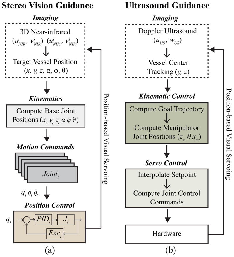
The motion control scheme of the robot (Fig. 3) consists of three phases—NIR stereo vision-based servoing, US-based servoing, and finally the needle insertion using force guidance. The first phase involves extracting the 3-D position of the insertion site from the stereo images, and directing this coordinate to the robot. This positions the end-effector unit over that location, aligning the needle with the vessel orientation. Desired joint angles are derived from the kinematics of the eye-in-hand camera configuration, and low-level position commands are sent to the motor drivers. The Cartesian gantry utilizes bipolar stepper motors and controllers capable of high-resolution micro-stepping (0.19 μm) and high repeatability (<4 μm). Attached encoders provide the position and velocity about each joint. Conversely, the rotary stages in the gantry contain DC-brushed motors, actuated via positioning controllers (EPOS, Maxon Motors). In the second phase, the 5-DOF on the base positioning system are further utilized to make fine position adjustments once the US probe is lowered, to enhance visualization of the vessel.
Fig. 3.
Motion control scheme in which position data is extracted from the image sensors and used to guide robotic motions. (a) Stereo vision-based, and (b) US-based visual servoing. During the venipuncture, the force sensor helps compute the needle tip location, serving as the third method of feedback.
Once each actuator reaches the set point wherein the US probe is oriented and centered over the target vessel, the robot then finely positions the needle via the the 3-DOF on the manipulator. At this point, the US probe is lowered over the forearm to display a clear image of the vessel. The needle orientation is then adjusted in real-time based on inputs from the US image and force sensor to position the needle tip in the center of the vein. Extrapolating the vein center coordinates from the US image, and tracking the needle tip during the insertion, the desired needle tip position is modified to accommodate subtle tissue motion during the procedure. Finally, in the third phase, force and current signals measured during the needle insertion are registered with the US image data to confirm the puncture of the target vessel.
Position-based visual servoing was implemented, as opposed to an image-based approach for several reasons. Namely, the needle is not in the field-of-view of the cameras, thus there is no way to use an image-based servoing scheme for vision-guided tasks. For US-guided tasks, where the needle is in the field-of-view during the venipuncture, image-based servoing has several drawbacks [28], [29]. First, task singularities can arise in the interaction matrix potentially resulting in unstable behavior. Second, occlusion of the needle may occur in the US image due to the inherently noisy acoustic signals. During the venipuncture, the needle may appear as a discontinuous line segment, resulting in feature extraction errors and posing significant challenges in designing a suitable controller.
III. Experimental Methods & Results
A. Kinematic Workspace Simulations
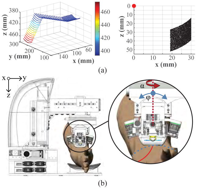
Forward and inverse kinematics experiments were conducted to evaluate the workspace of the system. To ensure that the device is able to operate along the length and upper circumference of the forearm, we computed the operating work envelope of the robot based on the derived kinematic equations. The travel range of the xr, yr, and zr prismatic joints provides a base rectangular work volume of 10×10×7.5 cm, and the rotational range of the revolute joints (α: ±90° and ϕ: ±30°) provides an additional envelope of 90 cm3 from any given position within the base work volume (Fig. 4a left). The manipulator adds a planar 14 cm2 range of motion lying parallel with the axis of insertion (Fig. 4a right). Table I summarizes the travel ranges of each actuator in the system.
Fig. 4.
(a) Kinematic joint range of the 5-DOF gantry (left), and 3-DOF manipulator (right). Points on the gantry plot indicate the position of the US probe transducer head; whereas the manipulator plot indicates the needle tip position (red dot represents the manipulator origin frame at the θ rotation axle center). (b) Illustration of the two rotational degrees of motion in the gantry (α and ϕ) used to align the manipulator unit with the vessel orientation.
B. Free-space Positioning
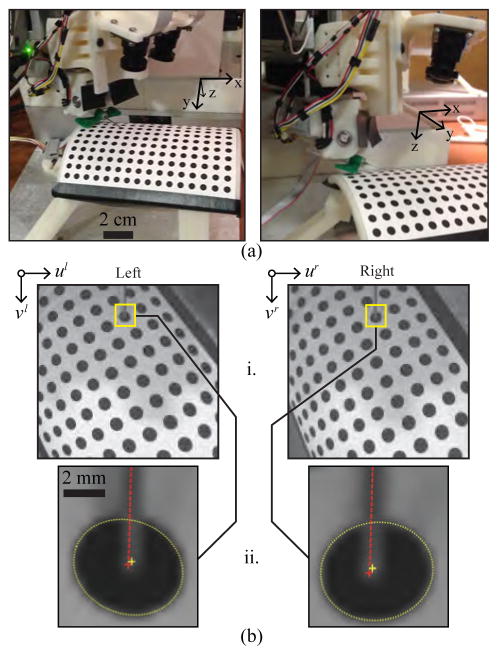
Free-space needle positioning experiments were then conducted on a cylindrical calibration platform (Fig. 5a) to assess the accuracy and repeatability of the robot over its reachable workspace. The calibration platform comprised 192 circular targets (ø4 mm, 7 mm center-to-center spacing) uniformly spaced over a cylindrical grid, with each target defining a unique, known 5-DOF pose (x, y, z, pitch, and yaw). The sixth-DOF (roll) was varied from −45–45° across the circumference of the platform.
Fig. 5.
Needle tip positioning studies. (a) Experimental setup (US probe removed to allow the needle to be seen in the images). (b) Position estimation of the needle tip and circle target. i. Images acquired and rectified based on the intrinsic camera parameters. ii. Image resolution increased 10x, and an ellipse detector used to segment circular targets (yellow dotted lines) and compute the centroids (yellow crosshairs). The needle is visible in both images (red dotted lines), allowing the needle tip to be extracted manually (red crosshairs).
To evaluate repeatability, three positioning trials were conducted for each of the circle targets. For each trial, the robot started in its home position, moved the needle tip to the desired 6-DOF pose, and returned to the home position. The desired 3-D position of each target was obtained from the CAD model of the robot. Target positions were also estimated from the right and left images acquired by the stereo imaging system (Fig. 5b). Here, an ellipse detector was implemented to segment and compute the centroid of each target, from which the 3-D coordinates were calculated based on the extrinsic camera parameters and the robot kinematic geometry. The needle tip was then extracted manually from each image and used to compute the 3-D needle tip location. Actual needle tip positions were then compared to the desired and estimated 3-D target positions to determine the error (accuracy) and standard deviation across trials (repeatability).
Fig. 5a displays the testing setup with the needle tip positioned at one of the calibration targets. As shown in Fig. 5b, the actual needle tip position was manually extracted from the stereo images after applying an ellipse detector to segment the target, and a line detector to highlight the needle. Table II presents the error between the circle positions in the CAD model and the positions estimated from the stereo imaging (row 1); the error between the desired and actual positions of the needle tip (row 2); the repeatability of the needle tip positioning (row 3); and finally the repeatability of the needle tip detection alone (row 4). The detection repeatability indicates the error inherent in the manual needle tip extraction process, which adds to the positioning repeatability.
TABLE II.
Needle tip positioning errors (n = 3 trials)—Units in mm.
| dx | dy | dz | 3D | |
|---|---|---|---|---|
| Mean – estimated vs. known position | 0.05 | 0.08 | 0.07 | 0.13 |
| Mean – needle tip vs. known position | 0.09 | 0.15 | 0.08 | 0.22 |
| Repeatability – needle tip positioning | 0.05 | 0.04 | 0.07 | 0.05 |
| Repeatability – needle tip extraction | 0.02 | 0.03 | 0.03 | 0.03 |
Over three trials, the 3-D positioning error was 0.22±0.05 mm, with the needle tip detection repeatability being 0.03 mm. These results imply that the robot has sufficient accuracy and precision to position the needle tip in vessels as small as ø1 mm, seen in pediatric patients. In addition, because these positioning studies were conducted using a cylindrical testing platform that mimicked the curvature of an adult human forearm, we were able to evaluate the performance of the robot over the operating workspace of the needle insertion task. This testing differed from positioning studies conducted on previous prototypes in that each target in the cylindrical calibration grid defined a unique 5-DOF pose for the robot to manipulate the needle. In comparison, previous studies used a planar calibration grid and only specified a 3-DOF Cartesian pose for the robot.
C. Stereo Vision Guidance
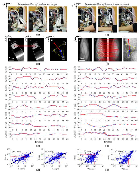
Tracking experiments were then conducted to evaluate positioning accuracy under stereo vision-guided servoing. The first set of experiments evaluated the needle pose errors as the robot positioned the needle to follow a moving calibration target (Fig. 6a). The calibration target comprised a grid of four circles lying on a plane (Fig. 6b). As the target was moved by freehand under the field-of-view of the cameras, the plane parameters were calculated based on the 3-D coordinates of each circle, which were extracted in real-time via an ellipse detector provided in LabVIEW. The plane parameters were then used to compute the 6-DOF pose of the circle target and, in turn, the desired pose of the needle. Fig. 6c displays the desired and actual positions of each robot degree-of-motion over a 60 sec period during the experiments. Fig. 6d displays the following errors as a function of the speed of the moving target. Both the linear and rotational errors were observed to increase with movement speed. At speeds of 10 mm/s and 10 °/s, the following error was 0.4 mm and 0.5°, respectively. Particularly at high speeds, state estimation filters (e.g. the extended Kalman filter commonly used in navigation robots [30], [31]) may help to reduce following errors by predicting future positions based on current system states.
Fig. 6.
Stereo vision tracking results. (a) Robot tasked with tracking a moving calibration target moved by freehand under the field-of-view of the stereo imaging system. (b) Stereo image pair showing the calibration target (i., ii.); the epipolar correspondence lines between the circular control points on the target (red lines); and the 3-D orientation of the target calculated from the plane parameters (iii.). (c) Desired and actual positions of each robot degree-of-motion over 60 sec of freehand calibration target tracking. (d) Linear (left) and rotational (right) following errors with respect to the speed of the moving target. (e) Robot tracking experiments repeated on human subject. (f) NIR contrast image highlighting veins in the forearm (i.); epipolar correspondence lines between SIFT features extracted from the left and right stereo images (ii., red lines); and SIFT feature points used to determine the 3-D position and orientation of the vessel target based on the tangent plane parameters (iii.). (g) Desired and actual positions of each degree-of-motion over 60 sec of human vessel tracking. (h) Following errors with respect to forearm movement speed.
Next, tracking experiments were repeated on veins identified on the forearm of a human subject by the NIR imaging system (Fig. 6e). To measure following errors over a range of speeds, the subject was asked to move their arm randomly under the device for a 60 sec period. During the experiment, the plane tangent to the forearm surface around the vessel target was estimated from the 3-D position of the vessel and the surrounding feature points (Fig. 6f). Similar to the previous tracking experiments on the calibration target, the plane parameters were used to determine the 6-DOF vessel pose and the desired needle pose. Unlike the previous experiments, which relied solely on ellipse detection, the feature points in the forearm images were extracted via SIFT. Only features present along the epipolar lines in both cameras were used in the pose calculations. Meanwhile, the actual vessel target was tracked using optical flow.
The desired and actual positions of each degree-of-motion during the human vessel tracking experiments are shown in Fig. 6g, and presented with respect to vessel movement speed in Fig. 6h. As before, following errors were higher when the motions were faster. At speeds of 10 mm/s and 10 deg/s, the following error was approximately 1.0 mm and 0.9 deg, respectively. The increased error compared to the calibration tracking experiments is most likely due to errors in the SIFT feature detector and optical flow tracking approach. In future studies we will evaluate following errors over a range of object tracking algorithms [32]. We will also assess whether the use of dense stereo correspondence algorithms or active stereo vision approaches, e.g. based on structured lighting, may improve the quality of the 3-D reconstruction and thereby reduce errors during tracking.
D. Ultrasound Guidance
In a third set of studies, we evaluated US-based visual servoing in a in vitro blood vessel phantom. The phantom consisted of a ø3 mm flexible silicone tube simulating the vessel, embedded within a compliant, fluid-like 0.2% agarose gel simulating the surrounding tissue. The phantom was contained in a 3-D printed enclosure, which was further mounted to the device.
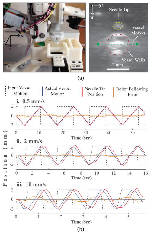
Vessel motions were simulated by moving the vessel laterally (Fig. 7a, left, y-axis) within the phantom over time periods of 60 sec. Controlled motion patterns were generated at varying speeds using a secondary motorized positioning system. The robot was then tasked with maintaining the needle tip position 1 mm above the moving vessel over the duration of the experiment. Frame-to-frame position changes of the vessel wall were tracked in each US image using optical flow. Fig. 7a, right shows a representative transverse US image of the surrogate vessel within the phantom (red dotted circle) and the tip of the needle passing through the transverse US imaging plane (yellow dotted circle). Also shown is the vessel’s lateral range-of-motion within the phantom (green dotted line).
Fig. 7.
US guided vein tracking. (a) Left—experimental setup showing the motorized phantom rig used to laterally displace the surrogate vein. Right—transverse US image depicting the vessel cross-section (red) and needle tip (yellow). (b) Robot following errors observed during side-to-side vessel tracking at i. 0.5, ii. 2, and iii. 10 mm/s. Errors refer to the difference between the known vessel location (determined from the vessel positioning stage) and the needle tip position (computed from the robot kinematics).
Fig. 7b compares vessel and needle tip positions at three lateral movement speeds (0.5, 2, and 10 mm/s). Table III summarizes the mean US tracking error (i.e. the error between the known vessel location, as set by the secondary positioning system, and the location estimated from the US images) and the mean robot following error (i.e. the error between the known vessel location and the needle tip position) at each speed. The US tracking errors were negligible at all three speeds, indicating that the frame rate of the US imaging system was sufficient within the tested speed range. Robot following errors, meanwhile, were observed to increase with movement speed; the mean error at 0.5 mm/s (0.003 mm) was about two orders less than the error at 10 mm/s (0.8 mm). As with the vision-based tracking experiments, incorporating state estimation filters may help to reduce the following errors at high speeds.
TABLE III.
US-based vein tracking results averaged over four square wave cycles (Error units in mm).
| Speed (mm/s) | US Tracking Error | Following Error |
|---|---|---|
|
| ||
| 0.5 | 0.004 | 0.003 |
| 2 | 0.006 | 0.046 |
| 10 | 0.004 | 0.794 |
E. Force Guidance
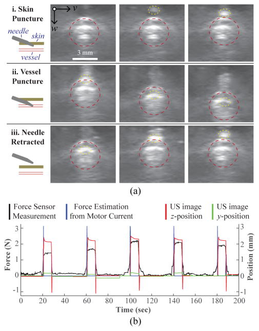
In the final set of experiments, we evaluated needle insertion under real-time force guidance using the same blood vessel phantom as described in Sec. III-D. Again, the ø3 mm vein was laterally displaced using the motorized stage (square wave, ±2 mm, 2 mm/s), and the robot was tasked with following the moving vessel target using the US image. For these studies, the robot positioned the needle tip directly above the vein for three motion cycles, and then the insertion system introduced the needle into the center of the vessel at 10 mm/s and 15°. Both the needle insertion and vein motion were halted once the force sensor detected the venipuncture. The robot then retracted the needle (at the same speed and angle as the insertion) and moved forward 2 mm in the x-direction to introduce the cannula on a new section of the vessel. In total, this process was repeated over five trials.
Fig. 8a displays a series of US image frames depicting the needle insertion steps. In addition to the force and current readings, we also monitored the z-displacement of the vessel from the US images during the needle insertion (Fig. 8b). The z-position measurement is the displacement from the original vein position, as measured by optical flow. Thus, a downward vessel movement results in a positive peak in the plot. As seen in Fig. 8b, there was no observable latency between the force, current, and z-position readings during the needle insertion. Interestingly, a relaxation phase—commonly seen in force sensing puncture events—was observed in the z-position signal following the venipuncture. Finally, since the needle was inserted along the longitudinal axis of the vein, minimal y-displacement was observed.
Fig. 8.
Force guided needle insertion. (a) US image frames depicting the needle insertion: i. needle pierces top phantom layer; ii. needle cannulates top vessel wall; and iii. needle is retracted. Vessel wall and needle tip highlighted with a dotted red and yellow border respectively. (b) z-displacement of the vessel extracted from the US images is shown to correlate with the force and current readings during the phantom cannulations (10 mm/s, 15°).
IV. Conclusion & Future Work
In conclusion, the control scheme deployed in the robotic venipuncture system was evaluated through a series of tracking experiments using stereo vision, US, and force guidance. Position-based servoing was implemented as opposed to an image-based approach, because the needle was not in the field-of-view of the cameras during vision-guided tasks, and was occasionally occluded in the image during US-guided tasks. Though position-based servoing depends on robot kinematics and image calibration parameters, this method worked well for our application, as demonstrated by our results.
Nevertheless, several limitations were observed when we evaluated the effects of motion speed on positioning accuracy. First, the robot lacked true dynamic controls, and instead, relied on set-points for trajectory planning. This was evident in our stereo vision experiments, where increased tracking errors were observed at higher motion speeds. Incorporating a dynamic motion control scheme in addition to the kinematic controls described in this paper may allow the system to rapidly adjust higher-order parameters, such as acceleration, to better adapt to sudden variations in motion speed. It is also possible that state estimation functions (e.g. the Kalman filter) may be implemented to predict future positions based on current trajectories, and that this may help to reduce following errors at high speeds. A second source of inaccuracy was the 3-D localization errors during the stereo reconstruction step. Implementing active methods of stereo vision based on structured illumination may help to improve the 3-D reconstruction quality in comparison to traditional passive stereo approaches.
Finally, the cannulation accuracy and precision of the device will be further evaluated in vitro over a wide range of realistic blood vessel phantoms, and in vivo, during lateral rat tail vein punctures. Through these studies, we will assess vessel motion speeds due to deflection and deformation during the venipuncture in order to understand whether any changes to the mechanical design of the system are required.
Acknowledgments
This work was supported by the National Science Foundation under Award Number 1448550, and by the National Institute Of Biomedical Imaging And Bioengineering of the National Institutes of Health under Award Number R01EB020036. The work of M. Balter was supported by an NSF Graduate Research Fellowship (DGE-0937373). The work of A. Chen was supported by the NIH/NIGMS Rutgers Biotechnology Training Program (T32 GM008339), and an NIH F31 Predoctoral Fellowship (EB018191).
The authors would like to thank Rutgers engineering students Alex Gorshkov and Alex Fromholtz for their contributions to the mechanical design and prototyping of the device. The authors would also like to thank the reviewers for insightful comments and suggestions on this manuscript.
Biographies
 Max L. Balter (M’14) received his B.S. degree in mechanical engineering from Union College (Schenectady, NY) in 2012, his M.S degree in biomedical engineering from Rutgers University (Piscataway, NJ) in 2015, and is currently pursuing his Ph.D. degree in biomedical engineering at Rutgers where he is a NSF Graduate Research Fellow. He is also the lead mechanical engineer at VascuLogic, LLC.
His research interests include medical robotics, computer vision, embedded system design, and mechatronics.
 Alvin I. Chen (M’14) received his B.S. degree in biomedical engineering from Rutgers University, Piscataway, NJ, in 2010, his M.S. degree in biomedical engineering from Rutgers University in 2013, and is currently pursuing his Ph.D. degree in biomedical engineering at Rutgers where he is a NIH Predoctoral Fellow. He is also the lead software engineer at VascuLogic, LLC.
His research interests include image analysis, computer vision, machine learning, and robotics.
 Timothy J. Maguire received his B.S. degree in chemical engineering from Rutgers University, Piscataway, NJ, in 2001 and his Ph.D. degree in biomedical engineering at Rutgers in 2006. Dr. Maguire has published over 20 peer-reviewed research papers and holds 8 issued or pending patents in the biotechnology and medical devices fields.
He is currently the CEO of VascuLogic, LLC, as well as the Director of Business Development for the Center for Innovative Ventures of Emerging Technologies at Rutgers.
 Martin L. Yarmush received his M.D. degree from Yale University and Ph.D. in biophysical chemistry from The Rockefeller University. Dr. Yarmush also completed Ph.D. work in chemical engineering at MIT. Dr. Yarmush is widely recognized for numerous contributions to the broad fields bioengineering, biotechnology, and medical devices through over 400 refereed papers and 40 patents and applications.
He is currently the Paul and Mary Monroe Chair and Distinguished Professor of biomedical engineering at Rutgers, the Director for the Center for Innovative Ventures of Emerging Technologies at Rutgers, and the Director for the Center for Engineering in Medicine at Massachusetts General Hospital.
Footnotes
This paper was recommended for publication by the Associate Editor upon evaluation of the reviewers comments.
Contributor Information
Max L. Balter, Department of Biomedical Engineering, Rutgers University, Piscataway, NJ, 08854, USA.
Alvin I. Chen, Department of Biomedical Engineering, Rutgers University, Piscataway, NJ, 08854, USA.
Timothy J. Maguire, VascuLogic, LLC, Piscataway, NJ, 08854, USA
Martin L. Yarmush, Department of Biomedical Engineering, Rutgers University, Piscataway, NJ 08854 USA, and also with Massachusetts General Hospital, Boston, MA 02108 USA
References
- 1.Taylor R, Stoianovici D. Medical robotics in computer-integrated surgery. IEEE Transactions on Robotics and Automation. 2003;19(5):765–781. [Google Scholar]
- 2.Moustris G, Hiridis S, Deliparaschos K, Konstantinidis K. Evolution of autnomous and semi-autnomous robotic surgical systems: a review of the literature. The international journal of medical robotics and computer assisted surgery. 2011;7:375–392. doi: 10.1002/rcs.408. [DOI] [PubMed] [Google Scholar]
- 3.Mahdi A, Khoshnam M, Najmael N, Patel R. Visual servoing in medical robotics: a survey. part i: endoscopic and direct vision imaging - techniques and applications. The international journal of medical robotics and computer assisted surgery. 2014;10:263–274. doi: 10.1002/rcs.1531. [DOI] [PubMed] [Google Scholar]
- 4.Mahdi A, Khoshnam M, Najmael N, Patel R. Visual servoing in medical robotics: a survey. part ii: tomographic imaging modalities - techniques and applications. The international journal of medical robotics and computer assisted surgery. 2015;11:67–79. doi: 10.1002/rcs.1575. [DOI] [PubMed] [Google Scholar]
- 5.Okamura A, Simone C, O’Leary M. Force modeling for needle insertion into soft tissue. IEEE Transactions on Biomedical Engineering. 2004;51(10):1707–1716. doi: 10.1109/TBME.2004.831542. [DOI] [PubMed] [Google Scholar]
- 6.Hadaway L. Needlestick injuries, short peripheral catheters, and health care worker risks. Journal of infusion nursing: the official publication of the Infusion Nurses Society. 2012;35(3):164–78. doi: 10.1097/NAN.0b013e31824d276d. [DOI] [PubMed] [Google Scholar]
- 7.Kobayashi Y, Onishi A, Watanabe H, Hoshi T, Kawamura K, Hashizume M, Fujie M. Development of an integrated needle insertion system with image guidance and deformation simulation. Computerized Medical Imaging and Graphics. 2010;34(1):9–18. doi: 10.1016/j.compmedimag.2009.08.008. [DOI] [PubMed] [Google Scholar]
- 8.Kobayashi Y, Hamano R, Watanabe H, Koike T, Hong J, Toyoda K, Uemura M, Ieiri S, Tomikawa M, Ohdaira T, Hashizume M, Fujie M. Preliminary in vivo evaluation of a needle insertion manipulator for central venous catheterization. ROBOMECH Journal. 2014;1:1–7. [Google Scholar]
- 9.Tanaka H, Ohnishi K, Nishi H, Kawai T, Morikawa Y, Ozawa S, Furukawa T. Implementation of bilateral control system based on acceleration control using fpga for multi-dof haptic endoscopic surgery robot. IEEE Transactions on Industrial Electronics. 2009;56(3):618–627. [Google Scholar]
- 10.Maghsoudi A, Jahed M. A comparison between disturbance observer-based and model-based control of needle in percutaneous applications. IECON 2012 - 38th Annual Conference on IEEE Industrial Electronics Society; 2012. pp. 2104–2108. [Google Scholar]
- 11.Cho J, Son H, Lee D, Bhattacharjee T, Lee D. Gain-scheduling control of teleoperation systems interacting with soft tissues. IEEE Transactions on Industrial Electronics. 2013;60(3):946–957. [Google Scholar]
- 12.Goldman RE, Bajo A, Simaan N. Compliant motion control for multisegment continuum robots with actuation force sensing. IEEE Transactions on Robotics. 2014;30(4):890–902. [Google Scholar]
- 13.Saito H, Togawa T. Detection of needle puncture to blood vessel using puncture force measurement. Medical and Biological Engineering and Computing. 2005;43:240–244. doi: 10.1007/BF02345961. [DOI] [PubMed] [Google Scholar]
- 14.Zemiti N, Morel G, Ortmaier T, Bonnet N. Mechatronic design of a new robot for force control in minimally invasive surgery. IEEE/ASME Transactions on Mechatronics. 2007;12(2):143–153. [Google Scholar]
- 15.Walsh G. Difficult peripheral venous access: Recognizing and managing the patient at risk. Journal of the Association for Vascular Access. 2008;13(4):198–203. [Google Scholar]
- 16.Ogden-Grable H, Gill G. Phlebotomy puncture juncture: Preventing phlebotomy errors – potential for harming your patients. Lab Medicine. 2005;36(7):430–433. [Google Scholar]
- 17.Juric S, Flis V, Debevc M, Holzinger A, Zalik B. Towards a low-cost mobile subcutaneous vein detection solution using near-infrared spectroscopy. The Scientific World Journal. 2014:1–15. doi: 10.1155/2014/365902. [DOI] [PMC free article] [PubMed] [Google Scholar]
- 18.Szmuk P, Steiner J, Pop R, Farrow-Gillespie A, Mascha E, Sessler D. The veinviewer vascular imaging system worsens first-attempt cannulation rate for experienced nurses in infants and children with anticipated difficult intravenous access. Anesthesia and Analgesia. 2013;116(5):1087–1092. doi: 10.1213/ANE.0b013e31828a739e. [DOI] [PubMed] [Google Scholar]
- 19.Stein J, George B, River G, Hebig A, McDermott D. Ultra-sonographically guided peripheral intravenous cannulation in emergency department patients with difficult intravenous access: A randomized trial. Annals of Emergency Medicine. 2009;54(1):33–40. doi: 10.1016/j.annemergmed.2008.07.048. [DOI] [PubMed] [Google Scholar]
- 20.Perry T. Profile veebot - drawing blood faster and more safely than a human can. Spectrum IEEE. 2013 Aug;50(8):23–23. [Google Scholar]
- 21.Chen A, Nikitczuk K, Nikitczuk J, Maguire T, Yarmush M. Portable robot for autonomous venipuncture using 3d near infrared image guidance. TECHNOLOGY. 2013;1(1):72–87. doi: 10.1142/S2339547813500064. [DOI] [PMC free article] [PubMed] [Google Scholar]
- 22.Balter M, Chen A, Maguire T, Yarmush M. The system design and evaluation of a 7-dof image-guided venipuncture robot. Robotics IEEE Transactions on. 2015;31(4):1044–1053. doi: 10.1109/TRO.2015.2452776. [DOI] [PMC free article] [PubMed] [Google Scholar]
- 23.Chen A, Balter M, Maguire T, Yarmush M. Real-time needle steering in response to rolling vein deformation by a 9-dof image-guided autonomous venipuncture robot. Intelligent Robots and Systems (IROS), 2015 IEEE/RSJ International Conference on; pp. 2633–2638. [DOI] [PMC free article] [PubMed] [Google Scholar]
- 24.Lowe D. Distinctive image features from scale-invariant keypoints. Int Journal of Computer Vision. 2004;60(2):91–110. [Google Scholar]
- 25.Horn B, Schunck B. Determining optical flow. Artificial Intelligence. 1981 Aug;17(1–3):185–203. [Google Scholar]
- 26.Heikkila J. Geometric camera calibration using circular control points. Pattern Analysis and Machine Intelligence IEEE Transactions on. 2000;22(10):1066–1077. [Google Scholar]
- 27.Mahvash M, Dupont P. Mechanics of dynamic needle insertion into a biological material. IEEE Transactions on Biomedical Engineering. 2010;57(4):934–943. doi: 10.1109/TBME.2009.2036856. [DOI] [PMC free article] [PubMed] [Google Scholar]
- 28.Garcia-Aracil N, Perez-Vidal C, Sabater J, Morales R, Badesa F. Robust and cooperative image-based visual servoing system using a redundant architecture. Sensors. 2011;11(12):11 885–11 900. doi: 10.3390/s111211885. [DOI] [PMC free article] [PubMed] [Google Scholar]
- 29.Hutchinson S, Hager G, Corke P. A tutorial on visual servo control. IEEE Transaction on Robotics and Automation. 1996;12(5):651–670. [Google Scholar]
- 30.Kang Y, Roh C, Suh S, Song B. A lidar-based decision-making method for road boundary detection using multiple kalman filters. IEEE Transactions on Industrial Electronics. 2012;59(11):4360–4368. [Google Scholar]
- 31.Julier S, Uhlmann J. A new extension of the kalman filter to nonlinear systems. Int Symp AerospaceDefense Sensing Simul and Controls. 1997;3:182–193. [Google Scholar]
- 32.Yilmaz A, Javed O, Shah M. Object tracking: A survey. ACM Computing Surveys. 2006;38(4):1–45. [Google Scholar]


