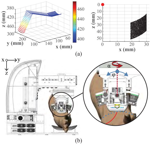
Fig. 4.
(a) Kinematic joint range of the 5-DOF gantry (left), and 3-DOF manipulator (right). Points on the gantry plot indicate the position of the US probe transducer head; whereas the manipulator plot indicates the needle tip position (red dot represents the manipulator origin frame at the θ rotation axle center). (b) Illustration of the two rotational degrees of motion in the gantry (α and ϕ) used to align the manipulator unit with the vessel orientation.

