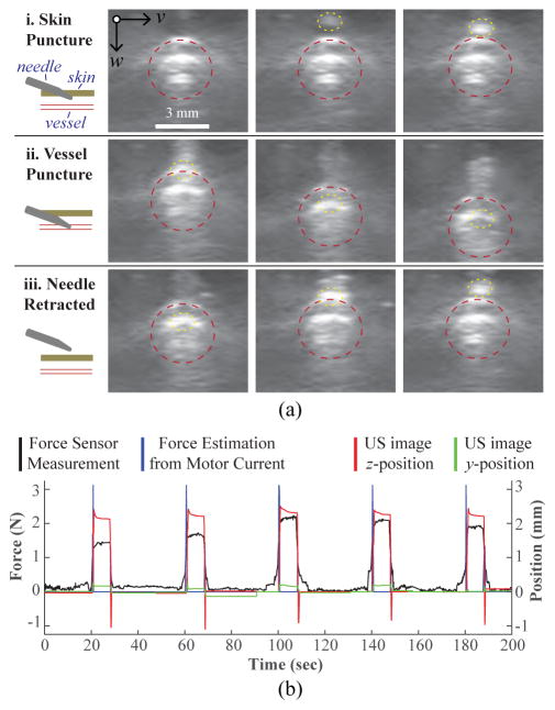
Fig. 8.
Force guided needle insertion. (a) US image frames depicting the needle insertion: i. needle pierces top phantom layer; ii. needle cannulates top vessel wall; and iii. needle is retracted. Vessel wall and needle tip highlighted with a dotted red and yellow border respectively. (b) z-displacement of the vessel extracted from the US images is shown to correlate with the force and current readings during the phantom cannulations (10 mm/s, 15°).

