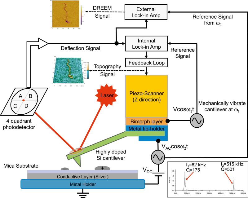
Figure 1. Instrumental Design for Simultaneous AFM and DREEM Imaging.
The AFM (MFP-3D, Asylum Research) is operated in repulsive oscillating (intermittent contact) mode with the cantilever mechanically vibrated near its resonance frequency (ω1 = 2π f1) (f1 = ~80 kHz for the cantilever used in this study) to collect the topographic information. To simultaneously collect the DREEM image, AC and DC biases are applied to a highly doped silicon cantilever (Nanosensors, PPP-FMR, force constant ~2.8 N/m), with the frequency of the AC bias centered on cantilever's first overtone (ω2 = 2πf2) (f2 ~500 kHz). An external lock-in amplifier is used to separate the ω2 component from the output signal and compare it with the reference input AC signal to generate the electrostatic amplitude and phase signals. The DC bias is maintained constant and is used to adjust the electrical vibration amplitude to produce optimal contrast in the DREEM images. In the current setup, the AC and DC biases can be adjusted from 0 V to 20 V and −2.5 V to 2.5 V, respectively. The inset shows the thermal motion of a typical cantilever used in our experiments as a function of the frequency. The frequencies and Q factors for the fundamental (f1, Q1) and first overtone (f2, Q2) frequencies are shown by each peak.

