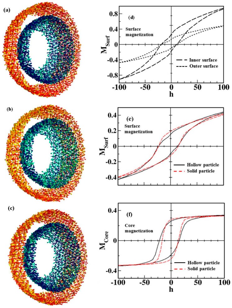
Figure 9.
Snapshots of the outer and inner surface spin configurations subject to varying magnetic fields (a) h = 100 (the maximum positive applied field), (b) h = 0 (remanence at the upper branch), and (c) h = −100 (the maximum negative applied field). Spins have been colored with a gradient from dark-red/dark-blue (outer/inner surface) for spins along the field direction to yellow/green (outer/inner surface) for spins transverse to the field direction. Only a slice of the spin configurations of a hollow nanoparticle close to the central plane and perpendicular to the field direction is shown; Low temperature (T = 0.1 K) simulated hysteresis loops for a hollow particle with the same dimensions as in the experiments (shell thickness of 2.5 nm) and surface and core anisotropy constants kS = 30 K and kC = 0.01 K. (d) Contributions of the spins at the inner (long dashed lines) and outer (short dashed lines) surfaces of the hollow particle to the total hysteresis loop with 1000 Monte Carlo steps. (e) Contribution of all surface spins to the total magnetization for the hollow MNP (continuous black line) is compared to that of a solid MNP with the same diameter (dashed red line). (f) The same as in panel (e) but for the interior spins contribution [44].

