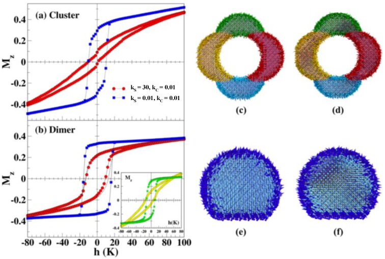
Figure 12.
Low temperature hysteresis loops simulated after cooling in a magnetic field hFC = 100 K as computed by Monte Carlo simulations of individual nanoparticles with cluster (a) and dimer (b) geometries. The non-magnetic metal is simulated as a hole in the middle for the cluster geometry and a sharp facet for the cluster. Panels (a,b) show hysteresis loops of a particle with cluster and dimer geometry, respectively, for two different values of the surface anisotropy constant: kS= 0.01 (blue squares) equal to the core value kC= 0.01, and increased surface anisotropy kS= 30 (red circles). The dashed lines in (b) stand for a spherical particle of the same size as the dimer. The inset shows the contribution of the surface (yellow circles) and core (green squares) spins of a dimer particle to the hysteresis loop for kS = 30. Snapshots of the spin configurations for cluster (c,d) and dimer (e,f) particles for kS = 30 (red circles) obtained at the end of the FC process (c,e) and at the coercive field point of the decreasing field branch (d,f) of the hysteresis loops. For clarity, only a slice of width 4a along the applied field direction and through the central plane of the particles is shown. Surface spins have darker colors and core spins have been colored lighter. Reproduced with permission from [37]. Copyright IOP Publishing, 2014.

