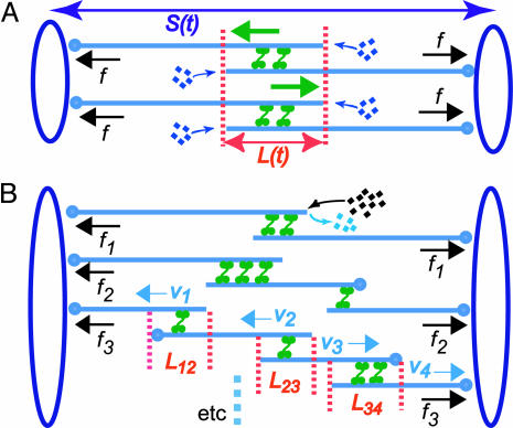
Fig. 3.
Model spindle geometry. (A) A simplified spindle with two identical arrays of ipMTs, each composed of two overlapping antiparallel MTs. Here, ipMTs have the same overlap, and their plus ends polymerize at the same rate. S(t) is the pole–pole distance, and L(t) is the length of the ipMT overlap. Green arrows indicate sliding of ipMTs by bipolar motors; black arrows indicate the motor-generated forces, equal to f for both ipMT arrays. (B) A realistic spindle with ipMT arrays composed of two, three, and four overlapping MTs. In the lower ipMT array, the overlap length between the parallel (L12 and L34) and antiparallel (L23) MTs and the sliding velocity of each MT (V1, V2, V3, and V4) is indicated. The dynamic instability of the plus ends, resulting in an average net polymerization, is shown only for the left MT in the top ipMT array. Forces generated by bipolar motors in different ipMT arrays (e.g., f1, f2, and f3) are different.

