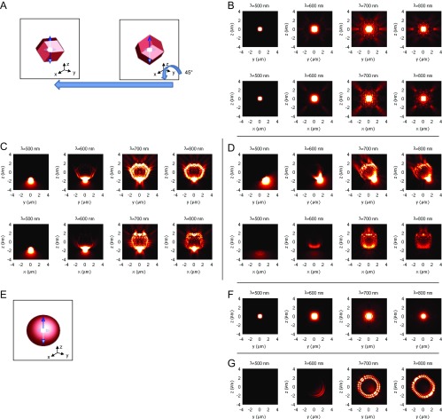
Fig. S6.
(A) Scheme showing the orientation of the RD considered in the main text (Left) and another with more symmetry (Right). The RD on the right and its orientation show the symmetry under 90° rotations with respect to x, y, and z axes as well as under reflection with respect to each plane (x–y, y–z, z–x). The orientation on the left can be achieved by rotating the RD on the right around the y axis by 45°. (B) FDTD-calculated emission profile () of a dipole at the center of the RD geometry in x–z (Top Row) and y–z (Bottom Row) planes. The microcavity center is (x,y,z) = (0,0,0) and = 5 µm, and the gold FF is 6%. The profiles are generated by incoherently averaging intensity over three dipole orientations aligned to the x, y, and z axes. (C and D) The same type of data as in B for the dipole locations presented in Fig. 3 A and B. (E–G) The same type of data for a spherical microcavity. F and G correspond to B and D, respectively.

