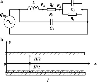
Fig. 2.

a Lumped parameter model for global hemodynamics of the parallel-plate flow chamber system. q in the input flow rate of the total system; q f the flow rate through the parallel-plate flow chamber; P A and P B the pressures at the two ends of the parallel-plate flow chamber, respectively; C 1 the compliance of the elastic A; C 2 the compliance of the elastic B; L the liquid inductance of silicone tube in the flow loop; R 1 the resistance of the resistance valve; R f the flow resistance of the parallel-plate flow chamber. b Schematic diagram of the parallel-plate flow chamber
