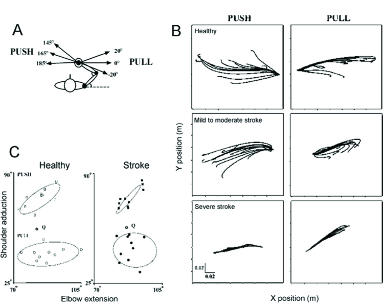
Figure 6.
Experimental design to identify referent hand positions. A: The subject sat in front of a computer screen with the trunk supported and the right arm attached to the handle of a double-joint manipulandum controlled by two torque motors. They were instructed to match the force of the motors by pushing the handle to the left (165°) or pulling it to the right (0°). For both initial conditions, 3 directions of the final force: 0°, 20° and -20° with respect to the direction of the initial force were used B. Examples of mean trajectories for each of the 12 unloading conditions for the push (left panels) and pull (right panels) directions in a healthy subject (top) and in participants with mild to moderate (middle) and severe (bottom) arm motor impairment. C. Referent arm configurations in elbow vs shoulder angle coordinates for the push (squares) and pull (circles) directions for healthy subjects (open symbols) and participants with a stroke (filled symbols). The 95% confidence ellipse for each group of points is indicated. Data are shown in reference to the initial configuration of the arm (open hexagons, Q). Figure shows that the range of regulation of R for each direction was restricted in patients with a stroke. Adapted with permission from Mihaltchev et al. (2005).

