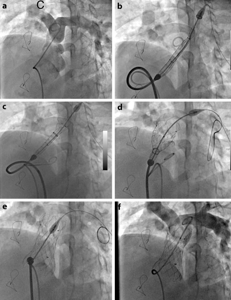
Fig. 4.
Fluoroscopic images demonstrating several steps of the implantation procedure. Basal angiogram in the main pulmonary artery in LAO and cranial projection to visualise pulmonary artery bifurcation (a), advancing and positioning Venus p‑valve delivery system in the RVOT with the tip advanced into proximal left branch (b), deployment of the distal end of the valve (c), deployment of the central part of the valve (d), Venus p‑valve completely deployed in an appropriate position (e) and final angiogram demonstrating a functional valve and patent pulmonary branches (f)

