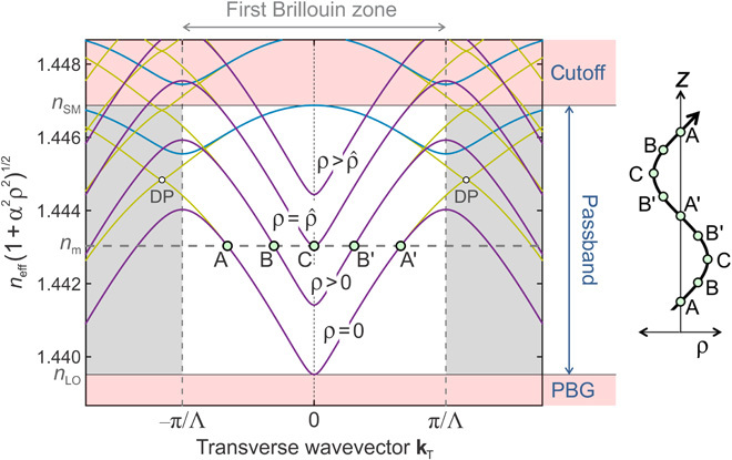
Fig. 2. Cuts through the dispersion surfaces of the highest-index passband in the two principal azimuthal directions (30° apart), numerically calculated at a wavelength of 818 nm for the coreless PCF used in the experiments.

kT is the wave vector component normal to the fiber axis, and Λ is the interhole spacing. The marked Brillouin zone is valid for the purple and blue curves. The dark yellow curves are for the cut-through at 30° to these curves and feature Dirac points (DPs); they are included to show that the shape at the bottom of the passband is approximately paraboloidal. The structure supports a full 2D PBG for axial wave vectors below the bottom of the first passband. On-axis in the twisted PCF (ρ = 0), and everywhere in the untwisted PCF, the passband is as marked, lying between regions of cutoff (neff > nSM) and PBG (neff < nLO). Close to the bottom and top of the passband, the contours of constant neff are very close to perfect circles. As the twist rate α increases, the entire dispersion surface lifts to higher values of index in proportion to α2ρ2 [the diagram will also tilt by an angle φ ≈ αρ (not illustrated)]. For the marked value of modal index nm, light propagates (A → B → C) for radii up to a certain maximum value, , beyond which point nm enters the PBG and the Bloch waves become evanescent. This causes Bloch wave rays to turn around and return to the axis (C → B′ → A′), creating the conditions for bound modes to form at values of nm, satisfying a separate resonance condition. The resulting path in real space is sketched on the right (note that it will be slightly distorted from a perfect sinusoid because the dispersion surface is not exactly a paraboloid).
