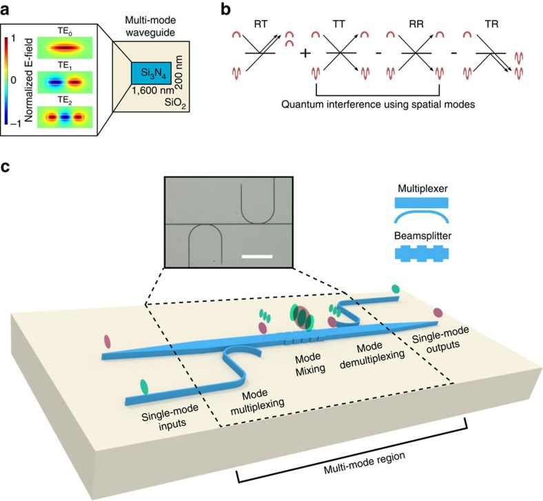
Figure 1. Quantum interference using a spatial mode beamsplitter.
(a) Simulation of transverse spatial modes in a multi-mode waveguide. (b) Schematic shows interference between two indistinguishable photons incident on the two input ports (or modes) of a beamsplitter, where the two input ports are the two spatial modes of a waveguide (TE0 and TE2). The four cases of probability amplitudes, in which TE0 and TE2 are reflected (R) or transmitted (T) are added or subtracted based on the unitary transformation of a beamsplitter. The arrows indicate whether the photons remain in the same mode or convert to the other mode. The destructive interference of the two cases that result in coincidences (RR and TT) leads to the characteristic HOM interference. (c) Schematic showing chip implementation of spatial mode multiplexing (asymmetric directional coupler) and spatial mode beamsplitter (nanoscale grating). The colours indicate the mode order within the multi-mode region of the device (red is TE0, green is TE2). The colour also shows the path that transfers single-mode inputs and outputs to the different spatial modes within the multi-mode waveguide. Wavelength (808 nm) and polarization (TE) are identical within each path. The inset shows a microscope image of the device. Scale bar is 160 μm.

