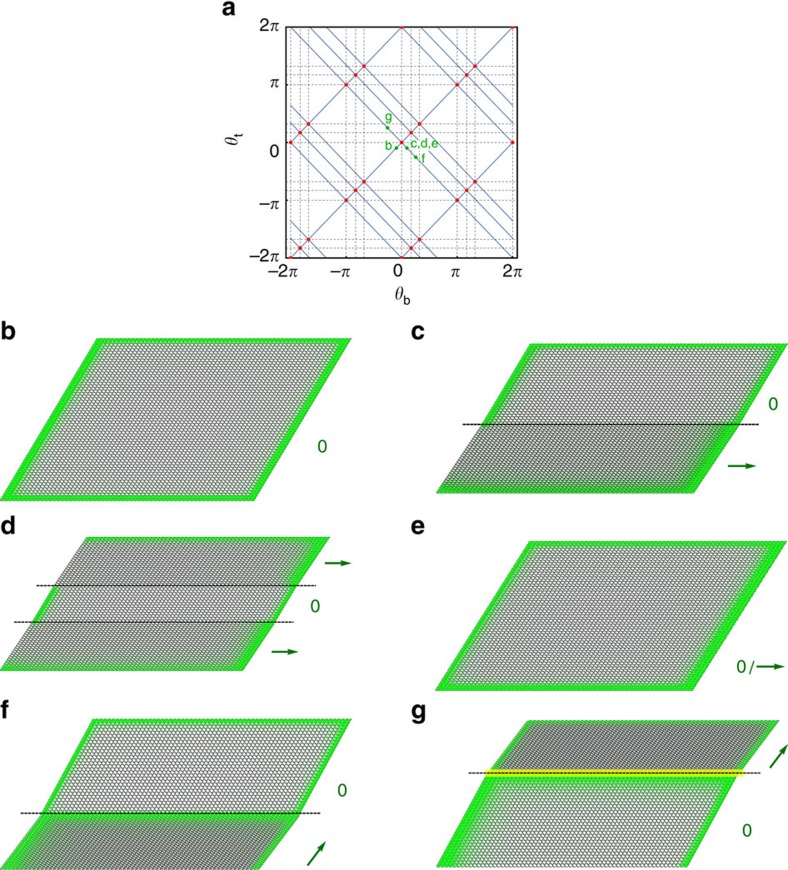
Figure 5. Manipulating edge modes via domain structure.
(a) Blue lines depict allowed configurations of a deformed kagome lattice, parametrized by the twisting angles (θt, θb) of two types of domains. At critical (red) points the two domains may be twisted in opposite directions, and continuing this twisting allows them to be separately polarized, passing through dashed lines. Green points denote the configurations shown in the remaining panels, wherein the spatial extent of the lattice's zero modes is shown in green. (b) Homogeneous, unpolarized lattice, with zero modes evenly distributed along the boundaries. (c) Lattice in which the domain below the dashed line has polarization pointing to the right, so that there are no zero modes on the left edge in the lower domain. In states such as (d), the domain structure may be chosen, so that only desired portions of the left edge (in this case, the middle of the edge) have zero modes and are deformable, while the rest are rigid. In (e), alternating rows are twisted in opposite directions, as though each row is its own micro-domain, such that half of the zero modes originating on the left wall have been shifted to the right. In (f), the configuration from (c) is twisted further, so that the bottom edge undergoes a second topological transition (passing through the dashed line in the top diagram), shifting zero modes onto the domain wall itself. In (g), the order of the domains is reversed as compared with (f), so that the domain wall acquires a line that can support stress (a self stress) rather than a zero mode.

