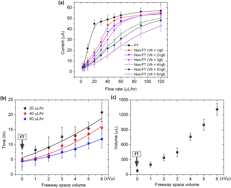
Figure 6.
(a) Maximum output current of the microfluidic FT and non-FT devices at different TSB medium flow rates. The non-FT devices used here have the freeway space volume Vfr varying from Vgf to 6Vgf (Vgf represents the volume of GF anode). (b) Time required for the FT and non-FT devices to obtain 80% of the peak output current as a function of freeway space volume of the devices. (c) Total volume of TSB medium consumed to obtain 80% of the peak output current as a function of freeway space volume of the devices.

