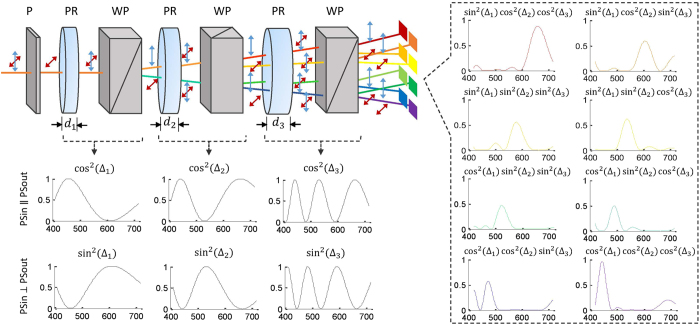
Figure 5. Illustration of the spatial and spectral splitting process for a broadband light beam.
The bottomleft shows the associated spectral transmission functions for each pair pf phase retarder and prism, and the right inset shows the spectral response for each bandpass channel. P, polarizer; PR, phase retarder; WP, Wollaston prism; PSin, input polarization state; PSout, output polarization state.

