Fig. 3.

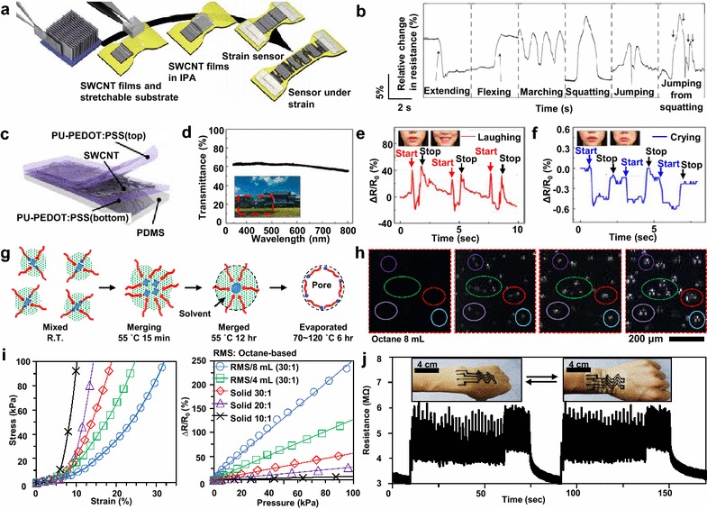
CNT-based wearable sensors. a Schematic of the fabrication process of the aligned CNT strain sensor. b Relative change in the resistance of the strain sensor patched onto the knee depending on his/her specific movements. (a–b Reproduced with permission from Ref. [13], © 2011, Nature Publishing Group). c Schematic exploded view of the transparent patchable strain gauge. d Transmittance of the strain gauge depending on the wavelength and a photograph showing the device placed on a picture (inset). e, f Relative change in the resistance of the strain sensor patched onto the face while e he/she is laughing and f crying. (c–f Reproduced with permission from Ref. [14], © 2015, American Chemical Society). g Schematics of the pore generation process according to the heat treatment conditions. h Successive images of the ECR under heat treatment, showing the gradually forming pores inside. i Stress–strain curves of various types of ECRs, obtained by deforming them and measuring the strain and applied stress (left), and the relative change in the resistance of the ECRs with respect to the applied pressure (right). j Change in the resistance of the wearable porous ECRs according to the repetitive bending and relaxing motions of the wrist. (g–j Reproduced with permission from Ref. [47], © 2014, WILEY–VCH Verlag GmbH & Co. KGaA, Weinheim)
