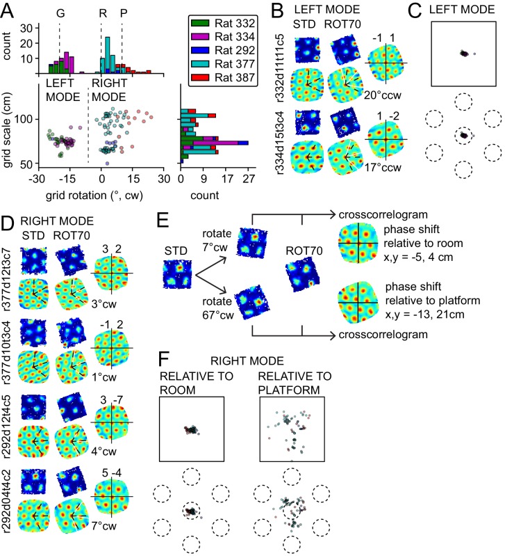
Figure 3. Bimodal response to platform rotation by 70° CW (ROT70).
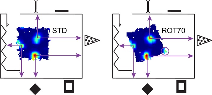
(A) A CW rotation of 70° allows the dissociation of the influences of the platform (‘P’ at 10° CW, corresponding to a 70° CW grid rotation because of the 60° radial symmetry of the grid), the room (‘R’ at 0°), and the geometric frame of the platform (‘G’ at 20° CCW, the minimum angle yielding a congruent square configuration for ROT70). This manipulation resulted in a bimodal grid-rotation response (abscissa). The left mode represents grids that were controlled primarily by the geometric frame of reference. The right mode represents grids that were controlled primarily by the room frame of reference (see illustration in Figure 3—figure supplement 1). Offsets of the modes from the predicted orientations indicate the counterweighing influence of a competing frame of reference in most rats. The 50 units in the left mode include 35 units that were recorded in the ROT20 manipulation (Figure 2B) on the same day. The 69 units in the right mode include 42 units that were recorded in the ROT20 manipulation on the same day. (B) Examples from the left (geometry-controlled) mode of the rotation distribution in A, illustrated as in Figure 2A. (C) Phase shifts in the grids of the left mode in A, illustrated as in Figure 2C. (D) Examples of rate maps from the right (room-controlled) mode of the rotation distribution in A. (E) Demonstration of phase shift calculation relative to room and platform reference frames for the last example in D. The grid rotates 7° CW in the room reference frame. This is equivalent to a 3° CCW rotational error relative to the physical platform’s rotation of 70° CW (after the 60° rotational symmetry of the grid is subtracted from 70°). The phase shift relative to the platform is therefore computed from the crosscorrelogram between the STD rate map rotated by 70° CW +3° CCW = 67° CW and the ROT70 rate map. (F) Phase shifts calculated relative to the room and platform reference frames as in E for all grids in the right mode in A. Note how grid phase (i.e. the position of the grid) is poorly controlled by the platform, but tightly controlled by the room.


