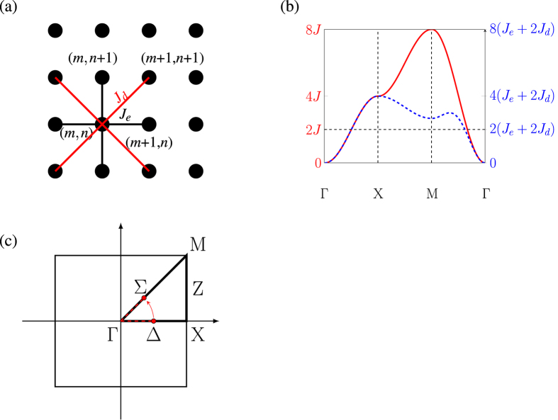
Figure 10.
(a) A Square lattice, where the black dots represent the lattice sites. The black lines is the standard nearest-neighbour coupling Je i.e. the coupling between (m,n) and (m ± 1, n), and between (m, n) and (m, n ± 1). The red lines represent the next-nearest-neighbour or the diagonal couplings Jd, which is the coupling between (m, n), (m ± 1, n ± 1). (b) Dispersion relation of a two-dimensional sheet along the high symmetry lines, with (blue-dotted) and without (red) the diagonal couplings (Jd). Along the Γ-X-direction, which corresponds to the principle axis in real space, both lines coincide. (c) A two dimensional k-space of a spin-sheet. Two red dots and the arrow indicated the initial and final position of a magnon that was launched along the principle axis and then bent to 45 degrees.

