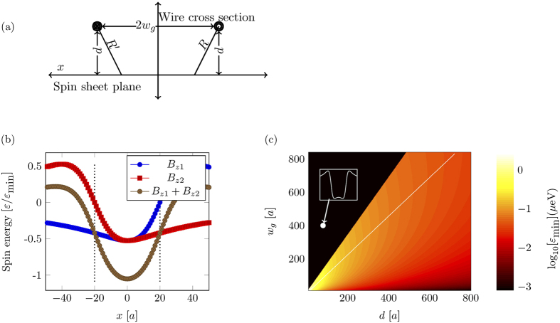
Figure 3.
(a) Cross section of a spin-guide. Two circles show the position of the wires, where the inner circle and cross inside each circle signifies the direction of the current. The horizontal line is the plane of the spin sheet. 2wg is the separation between wires and d is the distance between the spin sheet and the wires. (b) Onsite energy of spins inside the sheet due to individual ( and
and  ) and combined (
 ) magnetic field of two current carrying wires. Two vertical (dotted) lines show the position of the wires. The two wires form a potential well with depth εmin, which can guide magnons. (c) A pseudocolor plot of the depth, εmin, due to the magnetic field of the wires, located at the center of the potential. The black region is the region where the potential starts to split into two separate potentials and therefore leads to more complicated dynamics. The inset shows the shape of such a split potential with the parameters that lie inside the black region(d = 80a, wg = 400a). The white line marks the position of the maximum potential depth.

