Fig. 4.
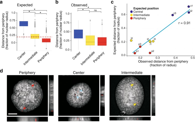
Validation of Chrom3D structures by FISH. a Expected radial distribution of ten FISH probes designed to the nucleus center (3 c probes), intermediate (4 i probes), and peripheral (3 p probes) areas, across 400 structures; *P < 2.2 × 10⁻¹⁶ (Mann–Whitney U tests). b Observed radial distribution of 1105 FISH signals for the ten probes analyzed in (a); *P < 10–4; ns, non-significant (Mann–Whitney U tests). Quantitative data for each individual probe are shown in Additional file 1: Figure S9b, c. c Correlation between observed and expected relative distance of FISH signals to the NP. d Examples of FISH images for each radial category (planar and orthogonal views); periphery, probe p1; center, probe c3; intermediate, probe i1. Bar, 5 μm

