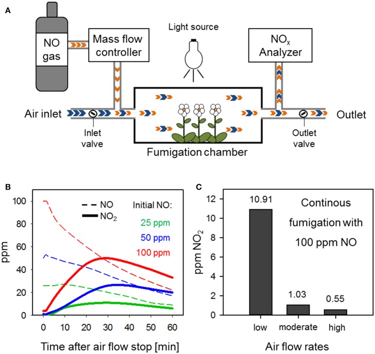
Figure 1.
An adequate set-up of a flow-through system for NO fumigation prevents NO2 formation. (A) Schematic diagram of an advanced flow-through system for NO fumigation. Blue arrows, air; orange arrows, NO. (B) NO2 accumulation in a fumigation chamber with disrupted air flow. Different initial NO concentrations (25 ppm = green, 50 ppm = blue, 100 ppm = red) where adjusted within the chamber before stopping the air flow (t = 0 min) by shutting the inlet and outlet valves. Changes in NO (dotted lines) and NO2 (solid lines) were measured over 60 min via an NOx Analyzer. (C) NO2 formation in a flow-through system is dependent on air flow rates. The NO concentration within the chamber was set to 100 ppm NO under low, moderate, or high air flow rate conditions and NO2 accumulation was measured 30 min after the flow-through system was equilibrated.

