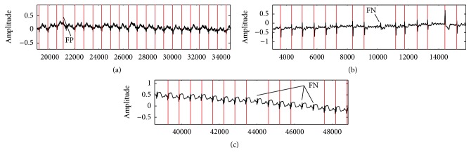
Figure 7.
(a) Detected QRS complex of ECG data (record s0020arem, lead avf). Records s0020arem and s0020brem include tall and sharp P-wave and T-wave. In this case, the QRS area has low energy. (b) Detected QRS complex of s0087lrem-lead 3. This case includes Irregular RR interval. (c) Lead v5 of s0089lrem. FN (false negative) is the number of not detected R peaks, and FP (false positive) is the number of noise spikes detected as R peaks. y-axis represents the amplitude, and x-axis represents the sample.

