Fig. 1.

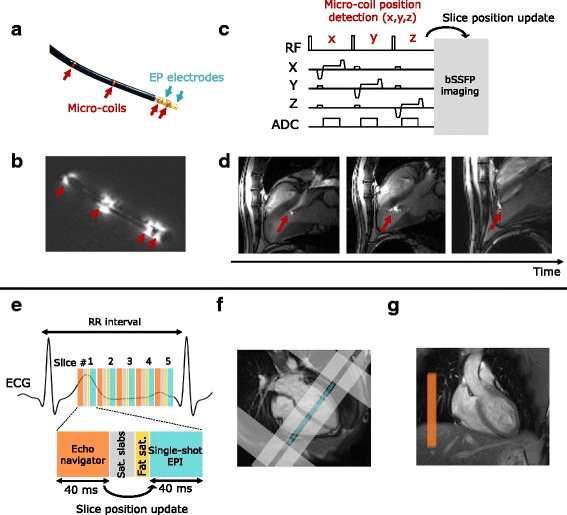
Imaging protocol for catheter navigation (a–d) and fast CMR thermometry (e–g) for ablation monitoring. a displays photograph of the CMR-compatible catheter equipped with 2 EP electrodes (blue arrows) and 4 micro-coils (red arrows). EP signals were measured between the two electrodes and the RF current was sent through the tip electrode. The associated magnitude image (b) of the catheter in water illustrates the utility of the 4 active markers which appear hyperintense whereas the catheter body stays hypointense. An interactive sequence (c) was run during the catheter manipulation. The micro-coil position was detected and used to update the position of the bSSFP imaging slices. Catheter tip (red arrows) could be visualized and followed as shown in (d). CMR thermometry was performed using a single-shot EPI triggered on ECG (e). Up to 5 slices were acquired depending on heart cycle duration. On healthy volunteers, imaging slices were positioned in short axis orientation (4 chambers view f, blue rectangle) and surrounded by saturation slabs (image f, gray rectangles): 2 along the FoV in the phase encoding direction to limit aliasing effect and 2 parallels to the imaging slices to reduce the signal of blood. A crossed-pair navigator was positioned on the dome of the liver (image g, orange rectangle on coronal view) to monitor respiratory motion at the lung/liver interface. The echo-navigator pulse sequence was run before each slice and the detected breathing stage was used to update the position of the following slice
