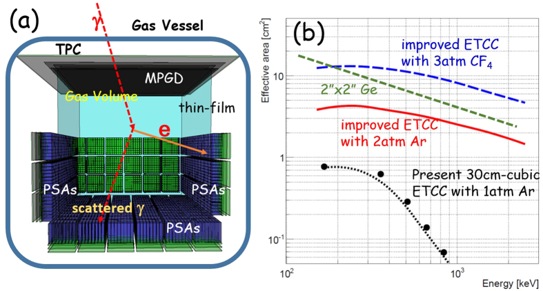
Figure 7. Schematic view and effective areas of future-planed ETCC.
(a) Schematic view of the inside of the TPC vessel of the revised ETCC. (b) Energy dependence of the effective areas. The filled-circles are the measured effective area of the present 30-cm-cubic ETCC with Ar 1-atm gas (SMILE-II ETCC), and the black dotted line is its simulated results. The red-solid and blue-dashed lines indicate the simulated effective areas for 30-cm-cubic ETCCs with 2-atm Ar gas and with 3-atm CF4 gas, respectively, with the PSA installed inside. Green dashed line is the effective area for the line gammas of 2″ (diameter) × 2″ (depth) Ge detectors.

