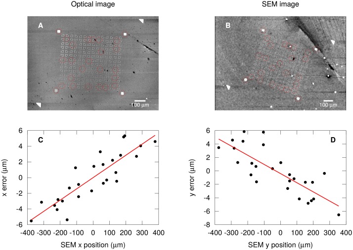
Fig 3. Nonlinear correction of electron-beam deflection.
(A) Optical image of Au alignment markers and selected markers with enhanced contrast for coordinate analysis (red circles). (B) SEM image of same device as A and selected markers with enhanced contrast (red circles). (C) Residual error in x coordinate of SEM beam deflection (black circles) that scales linearly with the SEM x coordinate (red line). (D) Residual error (black circles) in SEM y coordinate scaling linearly with the SEM y coordinate (red line).

