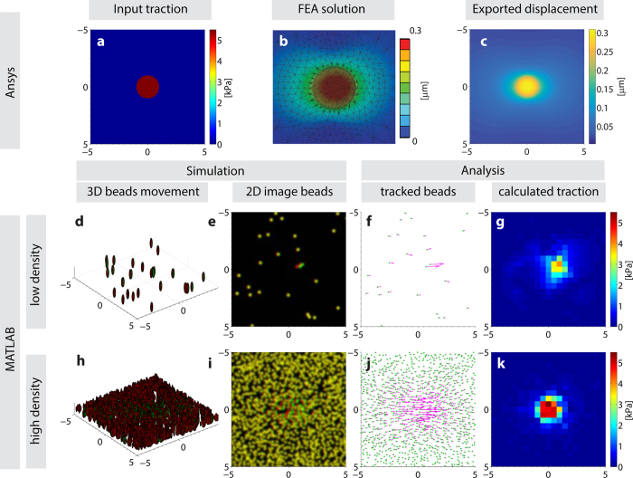
Figure 2. The simulation and evaluation environment operates using three main steps.
In the first step (a–c), a finite element analysis calculates the displacement field of a given traction input (a,b) which is exported to MATLAB (c and d–k). This deformation is then used to virtually translate 3D beads (d,h; red: before deformation, green: after deformation), and with user-defined inputs such as bead density (low: d–g, high: h–k) and location, simulated traction images can be generated in 2D (e and i). Using these images, the output of any TFM algorithm can be analyzed (f,g,j and k). As a sample result depicted here, a high bead density yields a more accurate force reconstruction.

