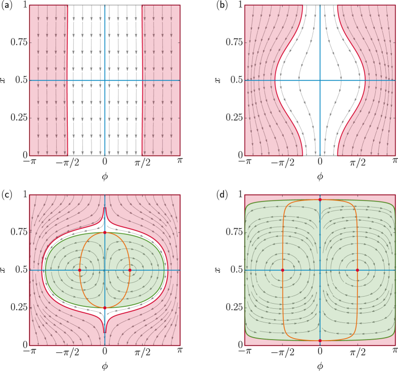
Figure 3. Noiseless regime, Dϕ = D0 = 0.
Velocity field  , see Eq. (7), for s = 2.5 and u/v0 = 100 (a), 2 (b), 0.5 (c), and 0.01 (d). The orange and blue curves denote respectively the (existing) x and ϕ nullclines of Eq. (7); their intersections (red dots) locate two stable (x = 1/2) and unstable (ϕ = 0) fixed points. Marked in red is the region of initial conditions corresponding to a negative drift velocity, i.e.,
  , and in green the trapping region, i.e., vx = u, where the particle oscillates inside the pulse in the co-moving frame (see text). For s < 0 the velocity field is characterized by two symmetric saddle points with x = 1/2, one attractor (ϕ = 0, x > 1/2), and one repellor (ϕ = 0, x < 1/2), not shown here.

