
FIGURE 4.
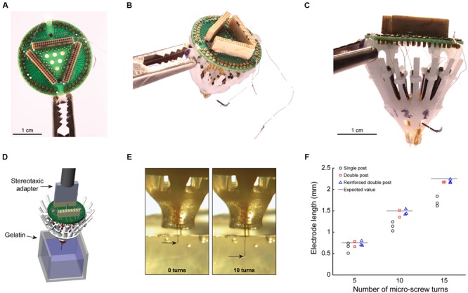
Empirical evaluation of electrode placement accuracy. (A) Top view of a completely loaded SLIQ hyperdrive (sans shield), showing a 96 channel EIB and Omnetics connectors. (B) Three-quarter view from above, with ground and EEG wires visible. (C) Side view, showing individually adjustable microdrives loaded with tetrodes, which protrude from the bottom piece. The anti-torque rails shown are the reinforced double pole design. (D) Illustration of the experimental setup to measure electrode displacement during driving. The SLIQ hyperdrive was attached to a stereotaxic via a custom adapter. (E) Measurement of electrode placement during driving. (F) Quantification of electrode length per turn of 15 full turns of the microscrew.