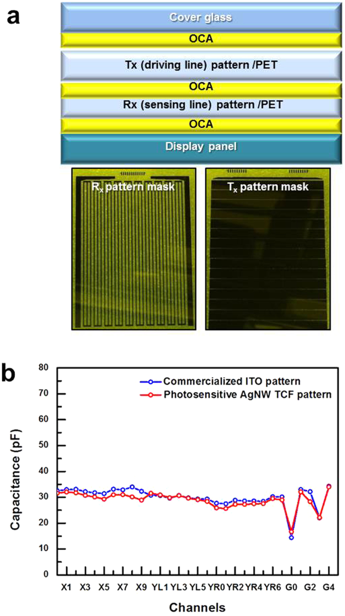
Figure 7.

(a) The upper figure shows the structure of the GFF-type TSP, which consisted of a cover glass and two TCF films. The lower figures show the Rx pattern (sensing line, y-axis pattern) and Tx pattern (driving line, x-axis pattern). (b) The capacitance of each electrode node of the TSP sensor, and a comparison of our TSP with the commercialized ITO one.
