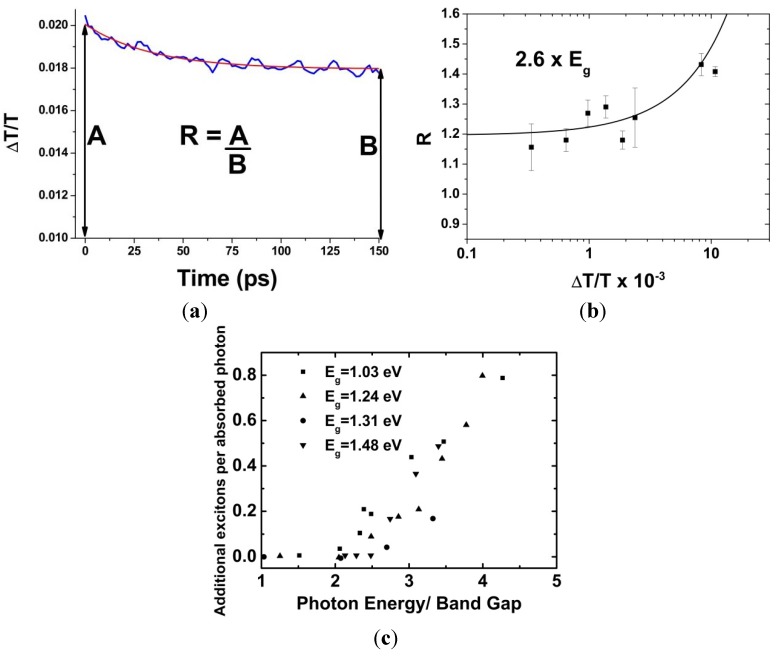
Figure 3.
(a) A typical signal obtained from a UTA experiment showing the fractional transmittance change, ΔT/T, as a function of time delay between the pump and probe beams. R is the ratio between the peak amplitude, A, and the plateau amplitude, B, where enough time has passed that all bi-excitons have decayed, but before any significant decay of single-excitons; (b) R as a function of fractional transmittance change, ΔT/T, for InP QD excited at 2.6 times Eg. The line is a fit to Equation (2), data from Reference [24]; (c) Additional excitons produced, (QY − 1), as a function of hv/Eg for InAs NQD of different Eg. hvth corresponds to the point where the rise in additional excitons begins, data from Reference [25]. Reproduced from Reference [26] by permission of the PCCP Owner Societies.

