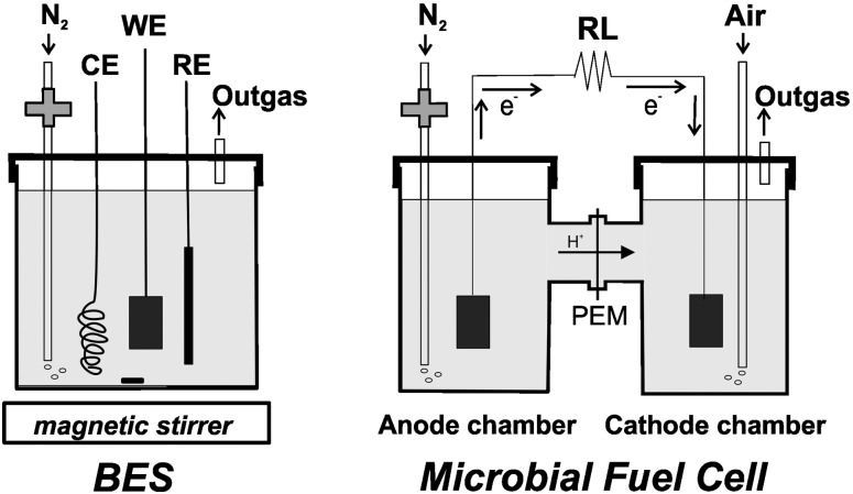
Fig 1. Schematic diagram of the bioelectrochemical set-up used in this work.
In the denominated bioelectrochemical system (BES) a working electrode (WE) is covered by a biofilm; CE and RE are immersed in the same solution (left). In the microbial fuel cell (MFC) the anode and cathode compartments were separated by a PEM (Nafion) membrane (right). N2 was filtered by a 0.22 μm membrane, as shown.

