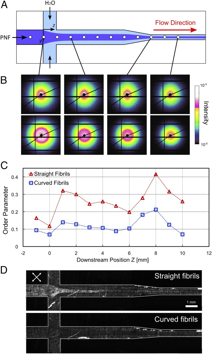
Fig. 4.
Alignment of PNFs in the microchannel. (A) Schematic of the channel geometry used for the SAXS experiments. White circles show the locations where in situ measurements were carried out. The experiments were performed at the center of the channel at different downstream positions. (B) μSAXS patterns at selected locations in the channel for straight (Upper Row) and curved (Lower Row) fibrils. (C) Local order parameters calculated from SAXS patterns as a function of downstream position z in the channel. The locations marked with circles in A correspond to the data points shown in C. (D) Images of the channel placed between two crossed polarization filters rotated 45° from the vertical axis (white arrows). For straight fibrils, birefringence due to the alignment is observed after the focusing step. In contrast, no birefringence is detected for the curved fibrils.

