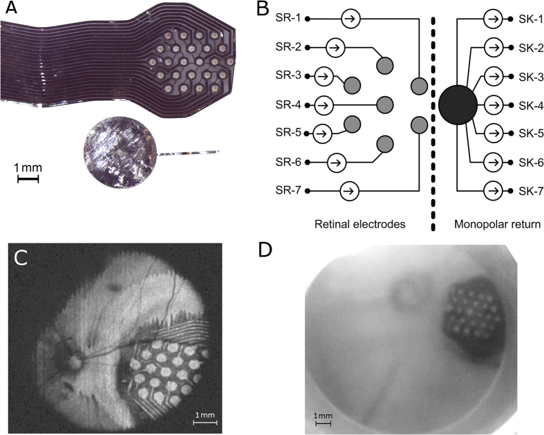
Figure 7.
Panel A illustrates the 24-channel retinal electrode array and the return electrode used during in vivo electrophysiology. Each electrode within the array has a diameter of 380 μm (area 0.113 mm2) and centre-centre spacing of 730 μm. The return electrode was approximately 3.5 mm in diameter. Panel B illustrates connections between the neural stimulator and the electrode array. Seven electrodes arranged hexagonally were connected to the source (SR-i) of seven independent current sources. The monopolar return electrode was connected to the sink of all channels (SK-i). Panel C is an optical coherence tomography image obtained after implantation. The voxels containing information on the electrode array were projected into a 2-dimensional image. Panel D shows an infrared image of the fundus of the same implanted eye.

