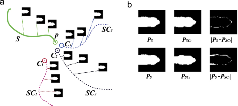
Figure 5. Initial trajectory generation and binary version of the head feature map comparison.
(a) S is the base part of the trajectory (green line) and the green circle indicates its end point p. SC1, SC2 and SC3are three linkable candidate segments that satisfy the specified spatial-temporal conditions. (b) Comparison of the binary version of the head feature maps in S with their counterparts in SC1 and SC3.

