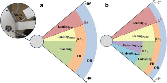
Fig. 2.

a A picture of the slack in the cable connecting the upper spring to the upper module and schematic representation of weight compensation regions of the exoskeleton alone, as described in the Methods. b Weight compensation regions after fitting arm into the exoskeleton, as described in the Discussion (SA, slack angle; BAE, exoskeleton balance angle; BAA, arm balance angle; FR, functional range; OR, operating range)
