Figure 2.
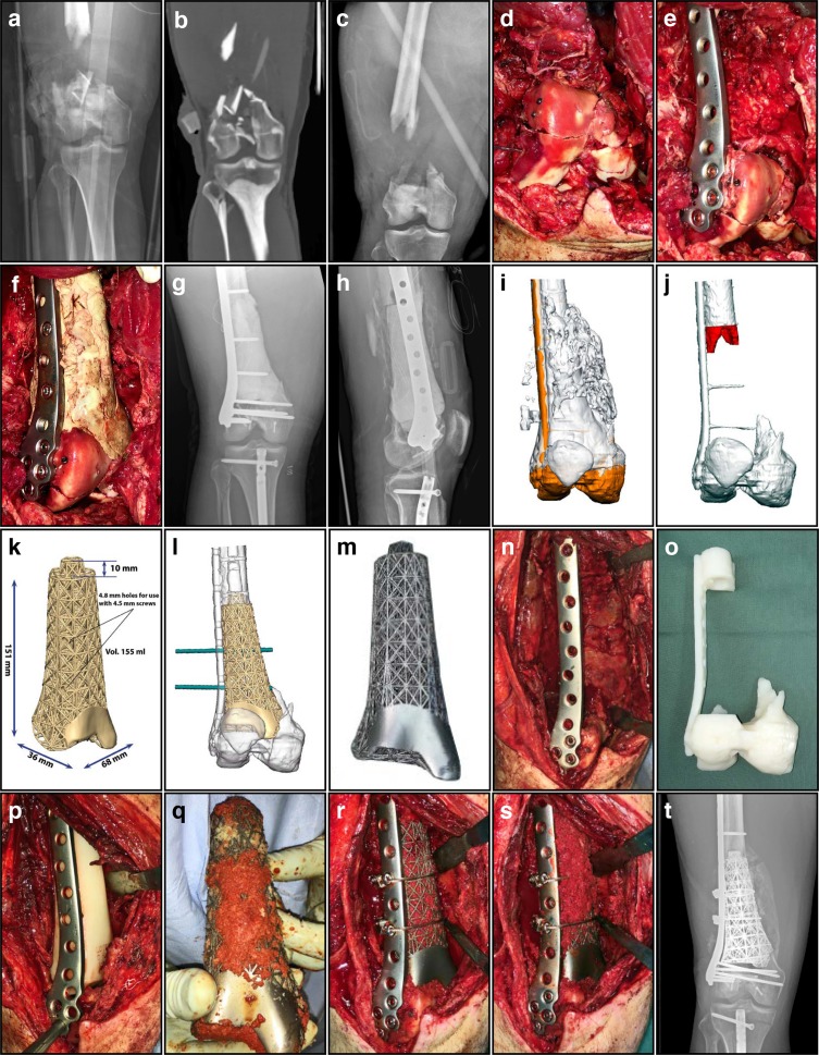
Metadiaphyseal distal femoral segmental defect (15.1 cm) – Grade 3A open fracture. (a) AP radiograph of this Grade 3A open R distal femur fracture immediately following the injury. (b) Initial CT scan demonstrating loss of bone stock and cartilage centrally, with less than 6 mm of bone adjacent to the intercondylar notch. (c) AP radiograph of the distal femur after initial debridement and spanning external fixation. (d) Intra-operative photos during the 1st stage, with reconstruction of the highly comminuted intra-articular extension of the fracture. (e) Intra-operative image showing the fracture reduced anatomically and then stabilized with a locked plate. (f) Intra-operative image during the 1st stage showing the PMMA spacer temporarily filling the defect, augmenting mechanical support of the distal segment while also providing a surface for the development of an induced membrane. (g) AP radiograph following stabilization with a lateral locked plate, incorporating an antibiotic-loaded PMMA spacer. (h) Lateral radiograph of the distal femur with plate and temporary PMMA spacer. (i) The patient-specific 3D printed titanium truss implant was produced after first conducting a virtual surgical procedure. (j) Additional bone was resected (red) to facilitate the actual procedure and to maximize contact and inherent stability. (k) Dimensions of the 3D printed titanium truss implant, designed with a tapered intramedullary extension proximally that increases stability significantly. (l) The truss implant design included trajectories for screw holes that correspond to the existing implant (green). (m) The final implant was produced with a polished surface to articulate with the patella, indicating extent of cartilage loss. The design of the implant very closely mimics the contours and dimensions of the original bone. (n) Intra-operative image during the second stage, with carefully opened and preserved membrane after the PMMA spacer was removed. (o) 3D printed acrylic model of the anticipated final skeletal defect, used to confirm satisfactory fit and alignment of the implant. (p) Intra-operative image showing insertion of a plastic template to assess the adequacy of the final resection, used as a trial before inserting the implant. (q) Before implantation, the truss construct was filled with autologous and allogeneic cancellous bone graft mixed with powdered vancomycin, then manually packed into the open cells of the truss implant. (r) Intra-operative image showing the truss implant filled with bone graft and inserted into the defect, with additional fixation including two cerclage cables. (s) Intra-operative image during the second stage, showing additional bone graft packed over the anterior and medial aspects of the truss implant after definitive fixation was completed. (t) AP radiograph demonstrating early incorporation of the bone graft, with a solid column of dense bridging bone visible medially four months after the procedure.

