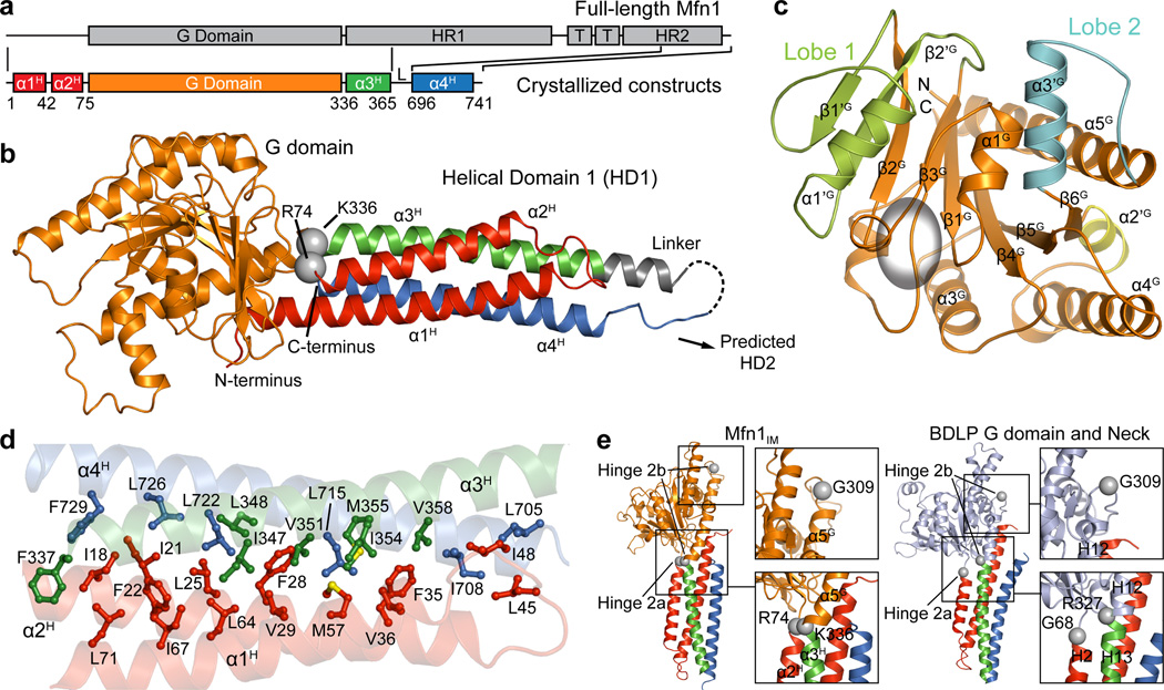
Figure 1. Overall structure of Mfn1IM.
a, Schematic representation showing the organization of Mfn1IM based on full-length Mfn1 with the conventional terminology: G domain, GTPase domain; HR1, heptad repeat region 1; T, transmembrane region; HR2, heptad repeat region 2. Elements for Mfn1IM are assigned according to the structure. L stands for the artificial linker. Borders of each element are indicated by residue numbers.
b, Structure of Mfn1IM. α-helices of HD1 are differentially coloured to specify their distribution on the primary structure as in a. The artificial linker is in grey. Disordered loop is shown as dashed lines. The Cα atoms of R74 and K336 linking G domain and HD1 are shown as grey spheres.
c, The G domain of Mfn1IM. Lobe 1, Lobe 2 and α2’G are colour-specified. The core region corresponding to Ras is coloured orange and the GTPase active site is indicated by an ellipsoid.
d, Hydrophobic network within HD1. Side chains of the residues involved in the network are shown in the same colour as the helices they belong to.
e, Comparison between the putative Hinge 2 of Mfn1IM and BDLP.

