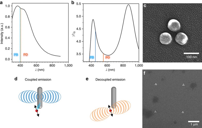
Figure 2. Spectral characteristics of the dyes used in this work and a schematic of their expected behaviour next to a plasmonic antenna.
(a) Simulated scattering spectra of an Al tri-disk system in DMSO (black) overlaid with the maximum absorption wavelengths for PB and PO dyes (blue and orange dashed lines, respectively). (b) γ/γ0 radiative enhancement of the system overlaid with the maximum emission wavelengths for PB and PO dyes (blue and orange lines, respectively). (c) SEM image of the Al tri-disk antenna. (d,e) Scheme showing the expected difference for coupled (that is, PB) and decoupled (that is, PO) emission from an equivalently positioned dipole in proximity with a simple plasmonic antenna. (f) SEM image showing four antennas from the Al tri-disk antenna-array.

