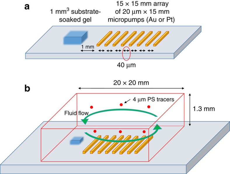
Figure 6. Schematic of the pump arrangement.
(a) The micropump system consists of an array (15 mm × 15 mm) of ∼200 catalytic strips of width 20 μm that are arranged in parallel with each other with a distance of 40 μm between them on a glass slide. (The image is not drawn to scale.) An agar gel (1 mm3) is soaked in the desired reagent and placed perpendicular to the array at a distance of 1 mm. (b) To observe the fluid flow, 2 μm (radius) fluorescent polystyrene tracer particles in buffer or deionized water were introduced into the system and the system was sealed.

