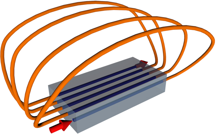
Figure 1. Scheme of the proposed implementation.

Illustration of the chip for implementing the photonic simulator in Eq. (2), where the arrows represent the input and output ports and the lines inside and outside the chip represent the waveguides and fiber connections respectively.
