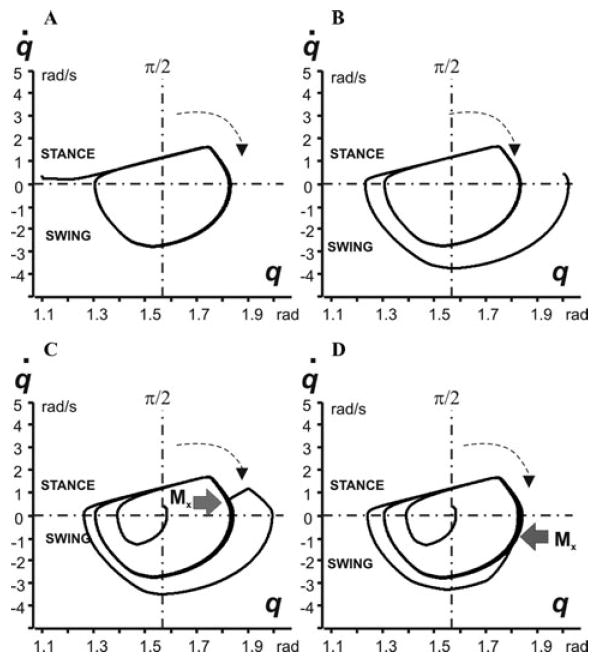
Figure 3.

Locomotor oscillations in the model represented as 2D (q, q̇) diagrams. In each diagram, the horizontal dash–dotted line at q̇ = 0 splits trajectory into the stance (top) and swing (bottom) parts; the vertical dash–dotted line corresponds to the vertical position of the limb (q = π/2); the arrows show the direction of movement. In diagrams (A) and (B), oscillations started from different initial angles (q0 at t = 0). (C) and (D) show the effect of disturbances, a moment of external force Mx = 150 N · mm applied for 100 ms in different phases of the step cycle (during stance in (C) and swing in (D)).
