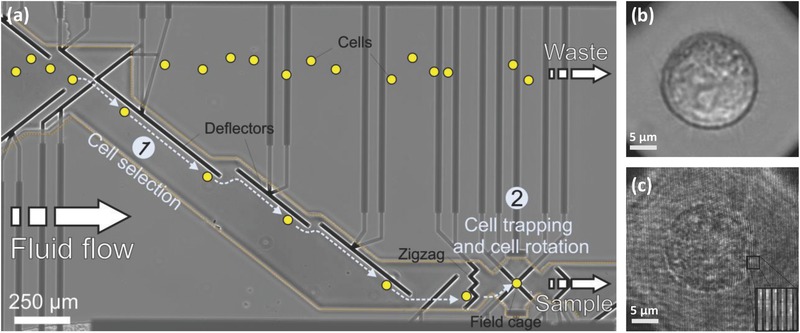
Figure 4.

Hybrid imaging in the DEP‐based microfluidic system. a) Microelectrode design and cell handling procedure in the microfluidic channel. Cells are represented by yellow spots. Electrodes from various DEP elements in the channel are marked in black. Electrode supplies are marked in dark gray and are passivated by a Si3N4 passivation layer (border line of passivation layer is marked by an orange dotted line). The DEP elements include deflectors and zigzag electrodes for laterally moving and retaining cells in the fluid flow, respectively. These elements allow the selection of a single cell from the bulk solution [Area (1)] to be trapped in the eight‐electrode field cage [Area (2)]. There, it is rotated around the axis of choice. The analyzed cells can be released from the channel via the sample outlet, whereas unprocessed cells are discarded to the waste outlet. b) Bright‐field microscopy image of an MCF‐7 cancer cell trapped in the field cage. Supplementary Video 1 (Supporting Information) shows bright‐field imaging of the cell handling in the channel and the rotation of the selected cell in the DEP field cage. c) Off‐axis image interferogram of an MCF‐7 cancer cell trapped in the field cage. The enlarged image at the bottom‐right shows the high‐spatial‐frequency off‐axis fringes from a selected area. Supplementary Video 2 (Supporting Information) shows the cell off‐axis interferogram from multiple directions of view during cell rotation in the DEP field cage.
