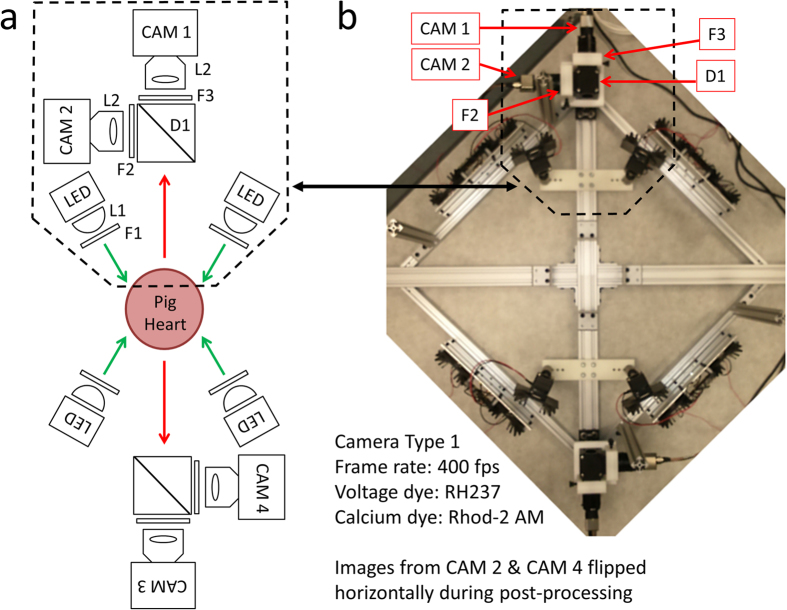
Figure 5. Optical Mapping System 2: Layout (Langendorff-Perfused Pig Heart).
(a) System schematic showing key components (see text for details). Two cameras and two LED light sources are used to image the heart from each point-of-view (green arrows: excitation light, red arrows: fluorescence emission light). One of the two cameras (CAM 1/CAM 3) is used to image transmembrane voltage while the other (CAM 2/CAM 4) is used to image intracellular free calcium. (b) Bird’s-eye view of the imaging and illumination subsystems outlined in (a).

