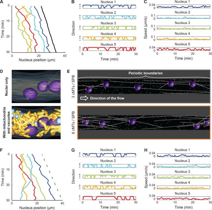
FIGURE 3:
Analyzing in vivo and simulated nuclear movements. (A) The position of five nuclei along time showing movement patterns. The centers of individual nuclei (1, blue; 2, turquoise; 3, green; 4, orange; 5, red) and the position of the hypha tip (black) were tracked along the course of the movie. Three reordering (bypassing) events can be seen by which two nuclei exchange their ranking along the hyphae. (B) The category of movement of each nucleus as a function of time. From the coordinates of each nucleus (1–5), the signed axial speed of movement, vx, was computed at every time point. The hypha growth speed, vh, was used as a threshold to categorize the movements as follows: forward, + (vh < vx); backward, – (vx < 0); and tumbling, 0 (0 < vx < vh). Colors match panel A. (C) Plots of absolute nuclei speed along time. Magnitude of nuclei speed along time (|v|) does not distinguish between forward and backward directions. Colors match panel A. (D) Snapshots of electron tomography models. Previously published data (Gibeaux et al., 2012, 2013) were used to generate snapshots showing (top) cMTs (green) and nucleation and organization from nuclei (purple)-embedded SPBs (yellow) and (bottom) the same nuclei within the cytoplasm crowd, including mitochondria (orange) and vacuoles (blue). (E) Snapshot of simulations. The simulations are performed in three dimensions within a cylinder with periodic boundaries in x, as indicated. The simulations contain five nuclei (dark violet), and each nucleus nucleates three (top) or six (bottom) cMTs (white lines). Cytoplasmic MTs are attached at their minus ends to one point at the surface of the nucleus (the SPB; orange ball) and grow at their plus ends. Inactive minus end–directed dynein motors are assumed to be present at each plus end. Each contact of a cMT plus end with a cortical dynein anchor (white dots) will induce pulling. The arrow indicates the direction of the applied cytoplasmic flow. (F) Nuclear positions along time taken from a simulation with six cMTs per nucleus. The x-coordinates of the center of individual nuclei are plotted in various colors (1, blue; 2, turquoise; 3, green; 4, orange; 5, red), and the dashed line indicates the applied flow speed. (G) The direction of motion of each nucleus along time. The motions were categorized exactly as in B. Colors match F. (H) Plots of absolute nuclei speed along time, exactly as in C. Colors match F.

