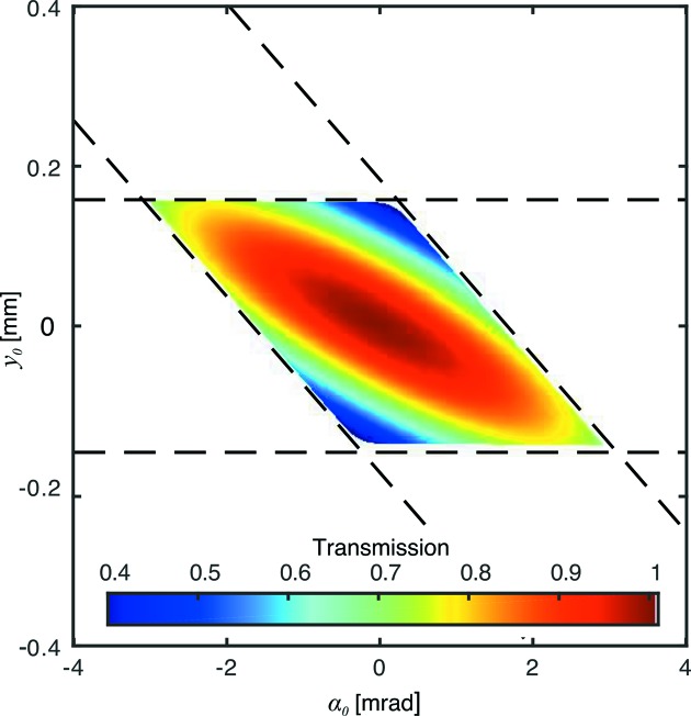
Figure 2.
Transmission function  for a typical beryllium CRL at 17 keV with parameters
  = 50,
= 50,  = 50 µm,
  = 2 mm,
  = 0.5 mm. The white region represents
  values excluded due to the constraints in equation (7), which can be approximated by two pairs of dashed lines corresponding to the entrance (horizontal pair) and exit (slanted pair) of the CRL.

